7.1 Parameter Lists
7.1.1 Interpreting the Servo Parameter Lists
7-2
7.1
Parameter Lists
7.1.1
Interpreting the Servo Parameter Lists
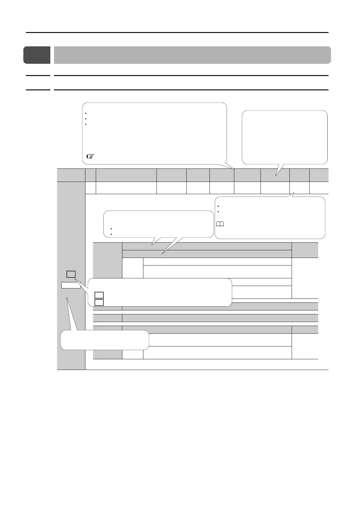
Parameter
No.
Size
Name
Setting
Range
Setting
Unit
Default
Setting
Applica-
ble Motors
When
Enabled
Classi-
fication
Refer-
ence
Pn000
2 Basic Function Selections 0
0000h to
10B1h
–
0000h All After restart Setup
–
Rotary Servomotor terms are used for parameters that are applicable
to all Servomotors. If you are using a Linear Servomotor, you need to
interpret the terms accordingly. Refer to the following section for
details.
Rotary: The parameter is used for only Rotary Servomotors.
Linear: The parameter is used for only Linear Servomotors.
All: The parameter is used for both Rotary Servomotors and Linear Servomotors.
The types of Servomotors to which the parameter applies.
Differences in Terms for Rotary Servomotors and
Linear Servomotors on page xii
Indicates when a change to the
parameter will be effective.
“After restart” indicates parameters
that will be effective after one of the
following is executed.
• The power supply is turned OFF
and ON again.
• The CONFIG command is sent.
• A software reset is executed.
n.X
Rotation Direction Selection
Reference
Movement Direction Selection
0
Use CCW as the forward direction.
–
Use the direction in which the linear encoder counts up as the for-
ward direction.
1
Use CW as the forward direction. (Reverse Rotation Mode)
Use the direction in which the linear encoder counts down as the
forward direction. (Reverse Movement Mode)
n.X Reserved parameter (Do not change.)
n.X Reserved parameter (Do not change.)
n.X
Rotary/Linear Servomotor Startup Selection When Encoder Is Not Connected
Reference
0
When an encoder is not connected, start as SERVOPACK for
Rotary Servomotor.
–
1
When an encoder is not connected, start as SERVOPACK for Lin-
ear Servomotor.
If there are differences in the parameters for Rotary
Servomotor and Linear Servomotor, information is
provided for both.
Bottom row: For Linear Servomotors
Top row: For Rotary Servomotors
Tuning
Setup
There are the following two classications.
For details, refer to the following manual.
Σ
-
7-Series
Σ
-7W SERVOPACK with
MECHATROLINK-III Communications References
Product Manual (Manual No.: SIEP S800001 29)
Symbols are provided when a parameter is valid only for a specic
prole.
•
:
Parameters that are valid only for a MECHATROLINK-II-compatible prole.
•
:
Parameters that are valid only for a MECHATROLINK-III standard servo prole.
M2
M3
This parameter applies to both axis A and
axis B. If you change the setting, the new
setting will be applied to both axes.

 Loading...


