3.1 Outline
3.1.1 Position Correction Table Block Diagram
3
Position Correction Table
3-3
This function is enabled after either of the following operations is performed during position
control.
• When using an absolute encoder
The SENS_ON (Turn Sensor ON: 23h) command is sent from the host controller.
• When using an incremental encoder
• The ZRET (Zero Point Return: 3Ah) command is sent from the host controller.
• The reference point is set (REFE = 1) using the POS_SET (Set Coordinate System: 20h)
command from the host controller.
3.1.1
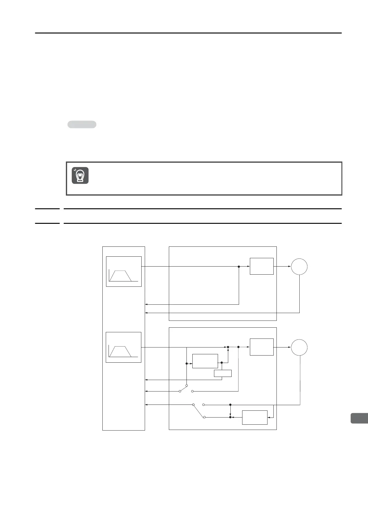
Position Correction Table Block Diagram
With each control cycle in the Servo (less than or equal to the communications cycle), the posi-
tion of IPOS (Internal Reference Position) is corrected by the Position Correction Table.
• The PSET and NEAR signals are output based on the corrected position.
• The software limit function uses the uncorrected position.
• This product assumes a system that issues commands for the same target position to the
master axis and slave axis.
To use this product for any other application, contact your Yaskawa representative.
If there is a deviation in the position of the origin, a deviation will occur in the values set in the
Position Correction Table, and the function may not work effectively. Configure the system so that
the position of the origin does not deviate.
SERVOPACK (master)
INTERPOLATE
/POSING
Servo-
motor
TPOS
APOS
Servo
control
IPOS
SERVOPACK (slave)
TPOS
APOS
IPOS’
Servo
control
+
+
IPOS
Δd
INTERPOLATE
/POSING
IPOS
IPOS
Position
Correction
Table
+
+
Host controller
Δd
Servo-
motor
Position
Correction
Table

 Loading...


