4.1 Outline
4.1.1 Synchronized Stopping Timing Chart
4-3
4.1.1
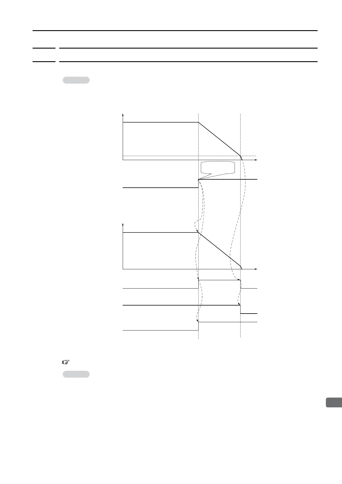
Synchronized Stopping Timing Chart
The following timing chart shows when Synchronized Stopping mode 1 or 2 is selected.
* During synchronized stopping, only emergency commands will be received.
Refer to the following section for details on CSTP_S (Synchronized Stopping Status).
Details of I/O Signal Status Bits on page 4-8
In Synchronized Stopping mode 3, both axes are almost simultaneously set to the servo OFF
state immediately after an alarm occurs. Therefore, CSTP_S which represents the synchro-
nized stopping status will not change, but it will instead remaining as the during normal oper-
ation status.
Ending Synchronized Stopping
When any of the following states occur, CSTP_S (Synchronized Stopping Status) in the SVC-
MD_IO field will become “0: During normal operation”, and synchronized stopping will end
with the servo OFF state.
• When feedback speed is less than Pn666 (Synchronized Stopping End Speed) (normal
end)
• When the SV_OFF or DISCONNECT command was received
• When the synchronized stopping axis changes to the servo OFF state due to an alarm or
for other reasons
After synchronized stopping ends, commands can be received from the host controller.
Speed
Time
Feedback speed
0
Pn666
(Synchronized Stopping
End Speed)
0
Alarm status
Speed
Feedback speed
Servo ON/OFF status
Time
OFFON
Normal status Alarm status
Normal status Warning status
Synchronized
stopping axis
ctive alarm axis
CSTP_S in
SVCMD_IO eld
A.97C
(Synchronized Stopping
Occurred)
During
synchronized
stopping*
During normal operation
Tracks the active
alarm axis and stops.
An alarm occurs.

 Loading...


