2.1 Ratings
2
SERVOPACK Ratings and Specications
2-3
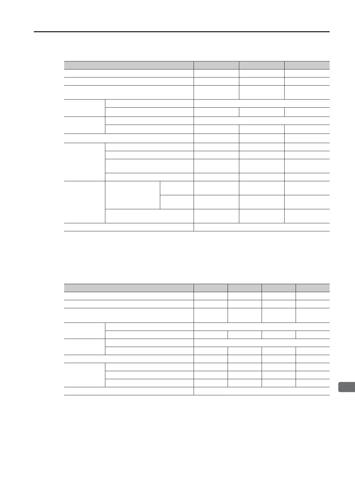
Single-Phase, 200 VAC
*1. If you use the SGD7W-5R5A with a single-phase 200-VAC power supply input, derate the load ratio to 65%. An
example is given below. If the load ratio of the first axis is 90%, use a load ratio of 40% for the second axis so
that average load ratio for both axes is 65%.
((90% + 40%)/2 = 65%)
*2. This is the net value at the rated load. However, a load ratio of 65% was used for the SGD7W-5R5A.
270 VDC
* This is the net value at the rated load.
Model SGD7W- 1R6A 2R8A 5R5A
*1
Maximum Applicable Motor Capacity per Axis [kW] 0.2 0.4 0.75
Continuous Output Current per Axis [Arms] 1.6 2.8 5.5
Instantaneous Maximum Output Current per Axis
[Arms]
5.9 9.3 16.9
Main Circuit
Power Supply 200 VAC to 240 VAC, -15% to +10%, 50 Hz/60 Hz
Input Current [Arms]
*2
5.5 11 12
Control
Power Supply 200 VAC to 240 VAC, -15% to +10%, 50 Hz/60 Hz
Input Current [Arms]
*2
0.25 0.25 0.25
Power Supply Capacity [kVA]
*2
1.3 2.4 2.7
Power Loss
*2
Main Circuit Power Loss [W] 24.1 43.6 54.1
Control Circuit Power Loss [W] 17 17 17
Built-in Regenerative Resistor
Power Loss [W]
8816
Total Power Loss [W] 49.1 68.6 87.1
Regenerative
Resistor
Built-In
Regenerative
Resistor
Resistance
[Ω]
40 40 12
Capacity
[W]
40 40 60
Minimum Allowable External
Resistance [Ω]
40 40 12
Overvoltage Category III
Model SGD7W-
1R6A 2R8A 5R5A 7R6A
Maximum Applicable Motor Capacity per Axis [kW]
0.2 0.4 0.75 1.0
Continuous Output Current per Axis [Arms]
1.6 2.8 5.5 7.6
Instantaneous Maximum Output Current per Axis
[Arms]
5.9 9.3 16.9 17.0
Main Circuit
Power Supply
270 VDC to 324 VDC, -15% to +10%
Input Current [Arms]*
3.0 5.8 9.7 14
Control
Power Supply
270 VDC to 324 VDC, -15% to +10%
Input Current [Arms]*
0.25 0.25 0.25 0.25
Power Supply Capacity [kVA]*
1.2 2 3.2 4.6
Power Loss*
Main Circuit Power Loss [W]
18.7 33.3 58.4 73.7
Control Circuit Power Loss [W]
17 17 17 17
Total Power Loss [W]
35.7 50.3 75.4 90.7
Overvoltage Category
III

 Loading...


