6-50
IM 701310-01E
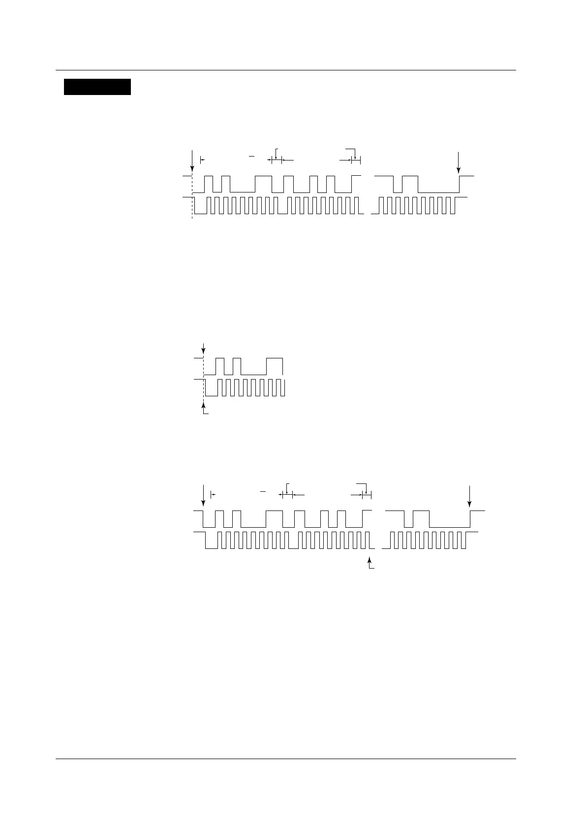
Explanation
This function triggers on I
2
C bus signals. The following figure shows the data format of
I
2
C bus signals.
Note that the /F5 or /F8 option is required for analysis of I
2
C bus signals.
...
...
SDA
SCL
Start condition
1
2
3
4
5
6 7
8
9
Acknowledge bits
Data byte
1
2
3
4
5
6 7
8
9
Stop condition
Address and R/W bits
Mode
Select the I
2
C trigger mode from Every Start, ADR & DATA, NON ACK, General Call, and
Start Byte/HS Mode.
Every Start Mode
When a start condition is detected, the DL9000 triggers on the falling edge of the SDA
signal.
SDA
SCL
Start condition
Triggers here
ADR & DATA Mode
When the address and data values match, the DL9000 triggers on the falling edge of the
9
th
SCL signal clock.
...
...
SDA
SCL
Start condition
1
2
3
4
5
6 7
8
9
Acknowledge bits
Data byte
Triggers here
1
2
3
4
5
6 7
8
9
Stop condition
Address and R/W bits
• Address
• You can set the address type to 7bit Address, 7bit + Sub Address, or 10bit Address.
• Set the address pattern in hexadecimal or binary notation. The address trigger
condition is met when the specified address pattern matches the input signal
address pattern.
• If you specify X, the condition is assumed to be met regardless of the corresponding bit
status.
• If a binary pattern contains any Xs, the corresponding hexadecimal display will be “$.”
6.15 Triggering on an I
2
C Bus Signal
 Loading...


