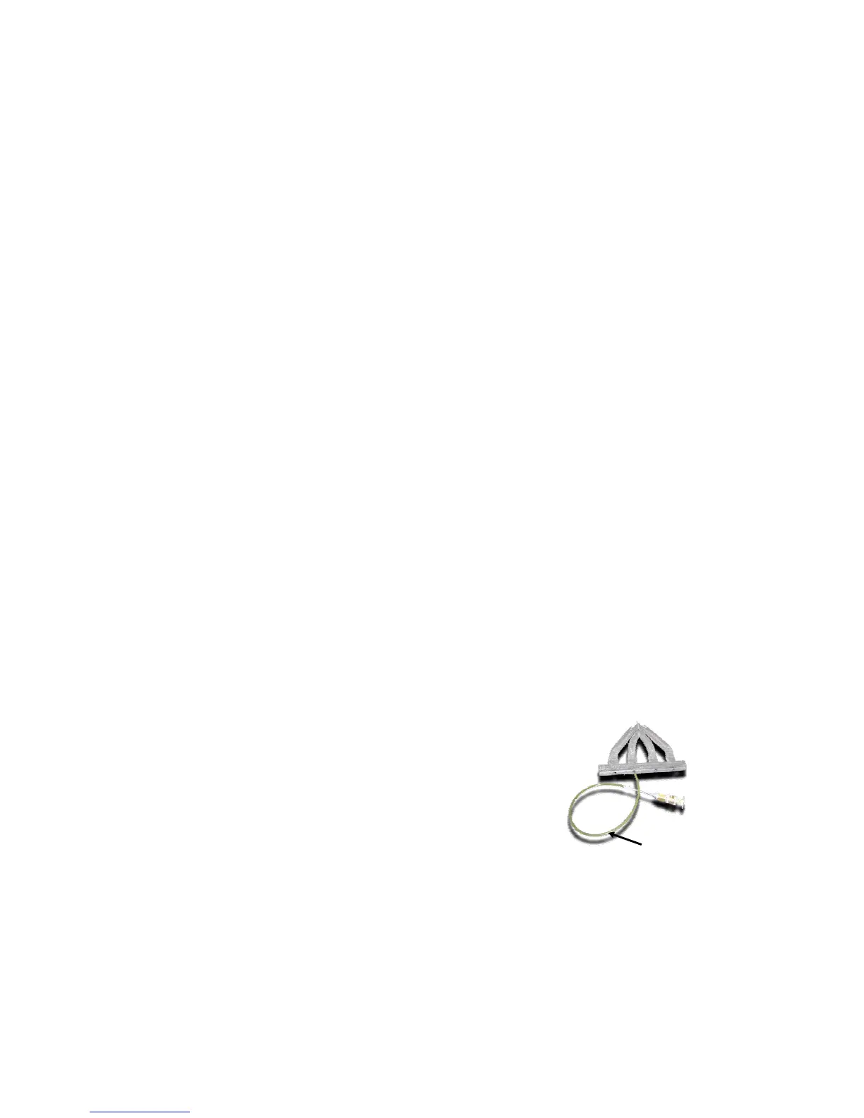
plastic hose like the one shown
above to reach ‘blind spots’
6.6 Parting Lines
The process for creating a mold in CAD software typically involves taking an object (the casting)
and subtracting it from a larger, encompassing object (the mold). The mold must then be split
along a generated surface or a plane. Traditionally, the parting line is very carefully chosen to
create a pair of patterns to form the cope and drag without undercuts, and minimize the number
of cores necessary.
Since ZCast molds are printed using the 3D Printing process, the choice of a parting line
becomes a much less demanding chore. The parting line can theoretically cut through any
portion of the mold cavity without regard for undercuts. Below is a list of the few things to
consider when choosing a parting line:
• Avoid thin edges – thin edges can break easily: during either handling or pouring.
• Keep cores intact – splitting cores will leave flash where the parting line passes through
resulting in metal fouling the core vent.
• Cores can sometimes be incorporated directly into either mold half. These ‘internal cores’
possess the benefit that they are always aligned and that no requirement exists that
venting pass through a parting surface.
• Position parting line where flash can be tolerated and/or ground off – putting the parting
line across a complex region without room to grind will limit the possibilities of finishing
the part.
• Keep parting line as far away as possible from core vents – since some metal can leak
along the parting line, be careful that it does not reach the openings for core vents. Metal
will potentially leak out of the mold and into the core, preventing the vent from performing
its function.
• Minimize the number of jogs – keep the design as simple as possible. The more angles
and steps in the parting line, the more difficult it will be to assemble the mold accurately.
6.7 Depowderability – Fixed Vs. Removable
Cores
Part depowdering refers to the removal of loose, unprinted
powder from the mold cavities following the printing process.
While the possibility to print complex geometries exists, such as
undercuts and runners that tunnel under the mold cavity, the risk
remains that all of the powder may not be removed during
depowdering. Loose powder left in the mold when metal is
poured has the possibility of affecting the outcome of the finished
casting by creating pockets or voids.
In order to avoid the aforementioned, ensure that your mold
has undergone a thorough removal of powder. In difficult to
reach areas such as blind channels and areas not visible, use
a small flexible hose like the one shown in figure 10 to extract
loose powder.
A 1/8” O.D. and 1/16” I.D. urethane tube is ideal because it slides firmly over the nozzle on the
ZD4
™
or ZD8
™
depowdering units.