2-8
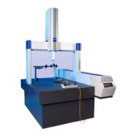
Description of the CMM
61211-1020202 CenterMax Operating Instructions
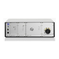
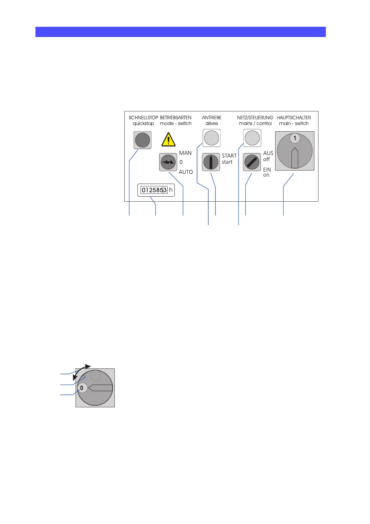
Operating elements of the control cabinet
The following operating elements and indicator lamps are located on
the control cabinet:
1 Main switch for power supply
2 Rotary switch for the control
3 Indicator lamp for control; green
4 Rotary switch for drives
5 Indicator lamp for drives; green
6 Key-operated switch for operating modes
7 Working-hour meter
8 Push-and-turn switch for quick stop; for cases of emergency
The functions of the operating elements are explained in the follow-
ing.
Power supply Main switch (1): The main switch is used to switch the power supply
of the coordinate measuring machine on and off.
a Direction of rotation for switching on and off; 0=On, 1=Off
b Detent opening; in position 0 the switch can be protected against
unauthorized switch-on.
c Position 0; power supply is switched off.
Control
Rotary switch (2) and indicator lamp (3): The rotary switch is used to
switch the control on. If it is in the ON position, the control is
switched on. The indicator lamp above the switch lights up.
Drives Rotary switch (4) and indicator lamp (5): The rotary switch is used to
switch the drives on.
Turn the switch clockwise. The switch does not remain in the new
position. It returns to its initial position.
53
187 6 4 2
a
b
c