7-2
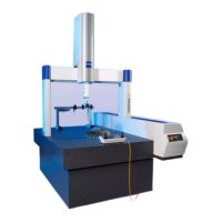
Measuring operation
61211-1020202 CenterMax Operating Instructions
What you should know!
Coordinate systems
There are three coordinate axes corresponding to the travel move-
ments: x, y and z. Together these axes form a machine coordinate sys-
tem. Two additional coordinate systems are required for exact
calculation: the workpiece and control coordinate systems. The coor-
dinate axes are assigned the letters G, W and S to identify of the coor-
dinate systems:
– Machine coordinate system; x
G
, y
G
, z
G
– Workpiece coordinate system; x
W
, y
W
, z
W
– Control coordinate system; x
S
, y
S
, z
S
For more information on the coordinate systems, please refer to the
➤ operating instructions for the measuring software.
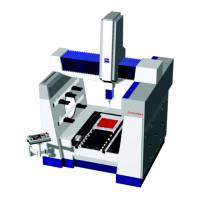
Probing directions
Six (=6) probing direc-
tions
Workpieces can be probed from six directions, ±x, ±y, ±z. The illustra-
tion below shows five probing directions. The rectangular block
shown cannot be probed in the positive z direction. However, in case
the block has lateral recesses and bores, it is possible to probe in the
positive z direction by using a corresponding probe configuration.
1Probe
2 Rectangular block (=workpiece)
3 Possible probing directions
4 Measuring table
1
2
3
4