ADJUSTMENT AND TESTS [AT DOCK]
Page 42
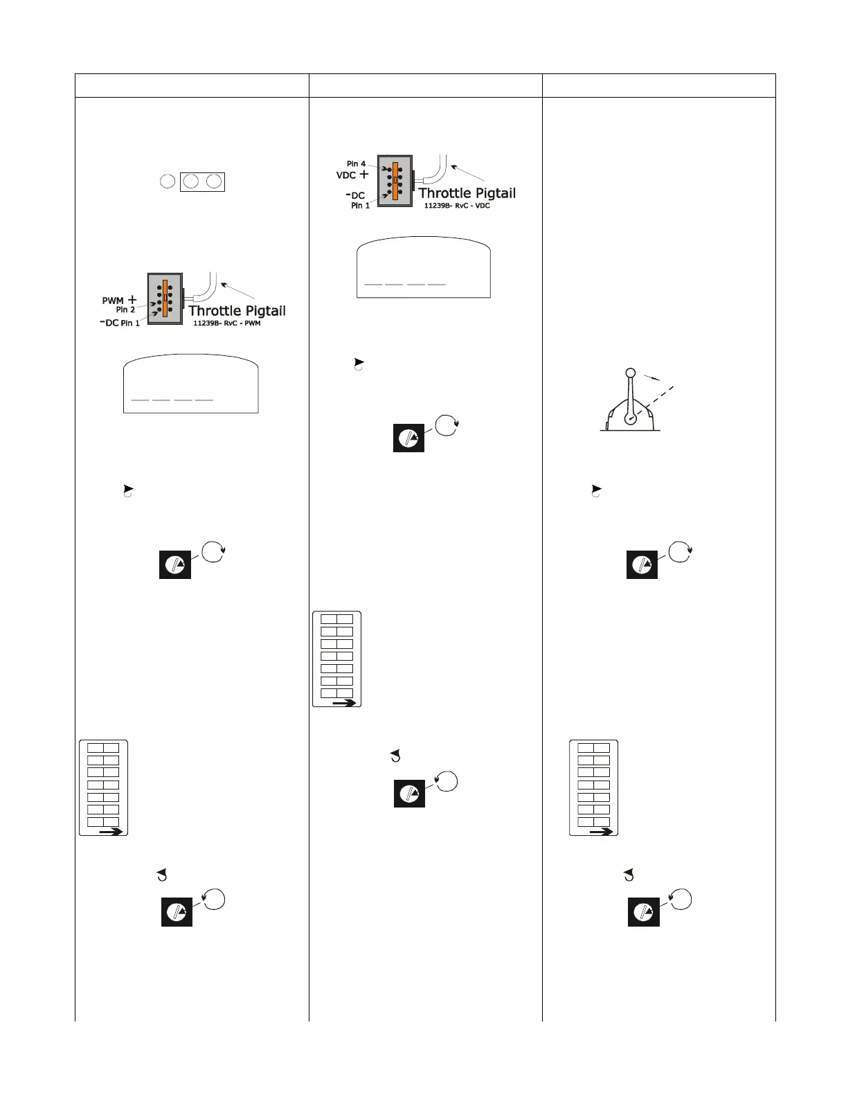
PWM (Duty Cycle) Voltage (VDC) Current (mA)
3) Move Jumper 6 on Auxiliary Board to
Pins 2-3 (voltage/current setting).
Refer to Figure 13:, page 25 Appen-
dix C System Drawing.
3)Connect the Multimeter to Pins 1 and 4
of the Throttle Connector (Refer to
Figure 29:).
3)Connect one Multi-meter probe to the
disconnected positive (+) throttle
signal wire.
4)Connect the Multimeter to PWM Pins
on the Throttle Connector (Refer to
Figure 29:).
4)Set Multimeter to the Voltage setting. 4) Connect the other Multimeter probe to
the terminal on the governor.
5)Set Multimeter to Duty Cycle setting. 5)Rotate Potentiometer R7 slowly clock-
wise until maximum throttle signal
is achieved. Refer to System Drawing
for R7 location.
5)Place the Control Head lever into the
Full Ahead position.
6)Rotate Potentiometer R7 slowly clock-
wise until maximum throttle signal
is achieved. Refer to System Drawing
for R7 location.
6)Store the value by depressing PB1
located on the Auxiliary Board. (Refer
to Figure 13:, page 25 for location of
PB1)
• The motor control relay will click
once to confirm the value has been
stored.
6)Rotate Potentiometer R7 slowly clock-
wise until maximum throttle signal
is achieved. Refer to System Drawing
for R7 location.
7) Store the value by depressing PB1
located on the Auxiliary Board.
(Refer to Figure 13:, page 25, for
location of PB1)
• The motor control relay will click
once to confirm the value has been
stored.
7)Reset all of the Dip
Switches to the Off position
(Run State)
7) Store the value by depressing PB1
located on the Auxiliary Board.
(Refer to Figure 13:, page 25 for
location of PB1)
• The motor control relay will click
once to confirm the value has been
stored.
8) Reset all of the Dip
Switches to the Off position
(Run State).
8) Return Potentiometer R7 fully counter
clockwise .
8) Reset all of the Dip
Switches to the Off
position (Run State).
9) Return Potentiometer R7 fully counter
clockwise .
9) Reconnect the Throttle Wire Harness to
the Throttle Pigtail at the Processor.
9) Return Potentiometer R7 fully counter
clockwise .
Table 2: Throttle Maximum Output Adjustments
1 2 3
VDC
%
Move To
Full Ahead
10161
0657-600
1234567
OFF
OF F
OF F
OF F
OF F
OF F
OF F
OF F
0657-600
1234567
OFF
OF F
OF F
OF F
OF F
OF F
OF F
OF F
-
1234567
OFF
OF F
OF F
OF F
OF F
OF F
OF F
OF F