AMT/PTD/PBX/0058/4/6/EN Installation and Maintenance Manual - Aastra 5000
Page 154 01/2011 Description des sous-ensembles
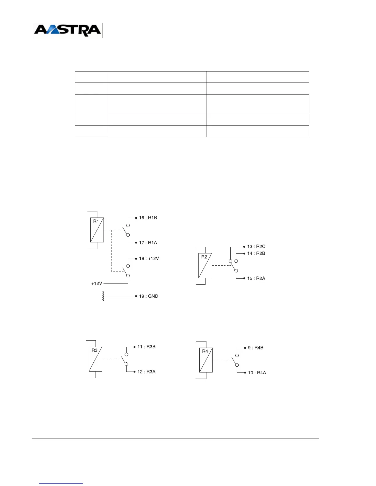
(1) The R1 Remote control relay delivers a +12V voltage through an 8 Ohm CTP
TABLEAU 4.9 DESCRIPTION OF IUCV CARD RELAYS
The following figure illustrates the R1, R2 and R3 relays of the iUCV card.
Note: The relay positions shown are the inactive states.
Figure 4.9
IUCV CARD RELAY CONTACTS
RELAYS FUNCTIONS STATE
R1 Remote control Work + 12 V (1)
R2 Alarm relays (assignment of alarms
by MMC). See Document [1]
Idle + Work (see section 5.6.3.2)
R3 Reduced service or Common Bell Work (see section 5.6.2.1)
R4 "Watchdog" alarm Work