AMT/PTD/PBX/0058/4/6/EN Installation and Maintenance Manual - Aastra 5000
Page 308 01/2011 Presentation of peripheral devices
5.6.3.2 Installation
Alarm bell setup requires no programming. It is implemented when you power on the
system.
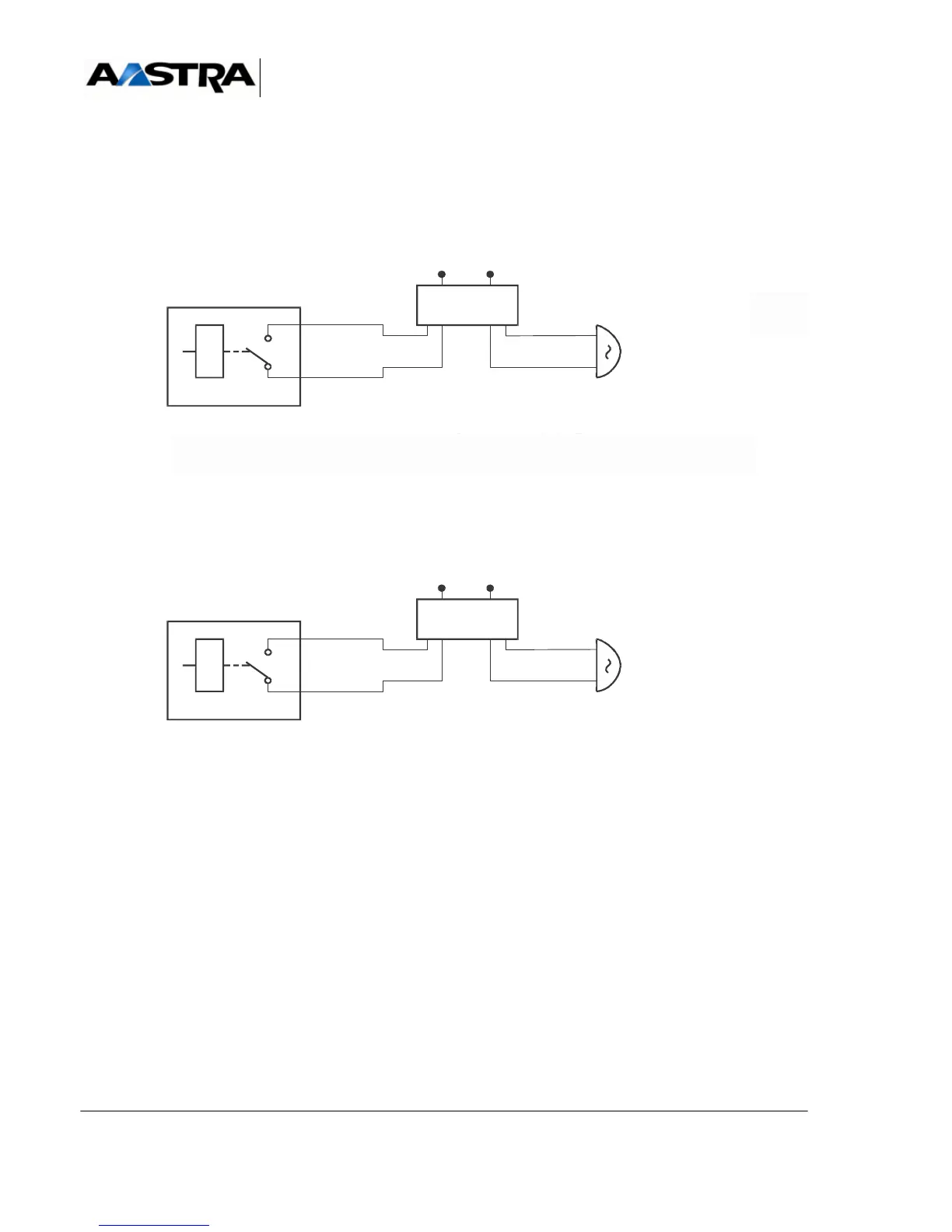
Figure 5.4 C
ONNECTING AN ALARM BELL (IUCV-D CARD)
R2: degraded operation alarm or synchronisation clock alarm relay
Figure 5.5 CONNECTING AN ALARM BELL (UCV CARD)
Carte IUCT
Secteur 230V
1 interface SLAT type TAT 524
La sonnerie d'alarme est commandée par le relais R3
Il est mis à votre disposition un contact sec sur J10 (courant max : 1 A)
Sonnerie
alternative
type 1000 Ω
Interface
sonnerie
SLAT
11
12
J10
R3
2
1
Secteur 230V
1 interface SLAT type TAT 524
votre disposition un contact sec sur J10 (courant max : 1
Sonnerie
alternative
type 1000 Ω
Interface
sonnerie
SLAT
J10
2
1
#ARTE)5#6$
2
La sonnerie d'alarme est commandée par le relais R2
Il est mis à votre disposition un contact sec sur J10 (courant max : 1 A)
Secteur 230V
1 interface SLAT type TAT 524
Sonnerie
alternative
type 1000 Ω
Interface
sonnerie
SLAT
2
1
#ARTE5#6
*!
,ASONNERIEDALARMEESTCOMMANDÏEPARLERELAIS2
)LESTMISÌVOTREDISPOSITIONUNCONTACTSECSUR*!COURANTMAX!
2