AMT/PTD/PBX/0058/4/6/EN Installation and Maintenance Manual - Aastra 5000
Page 230 01/2011 Description des sous-ensembles
4.13.4.3 Physical description (see Figure 4.37 )
Connectors
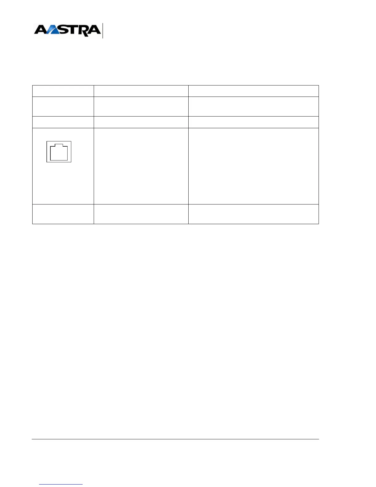
TABLEAU 4.45 DESCRIPTION OF LT2 CARD CONNECTORS
NAME FUNCTION/CHARACTERISTIC CONTACTS
J1 96-pin connector:
backplane connection.
J2 and J3 Not used
E1/T1) ISDN or PCM line connection
(transmit and receive pair)
RJ45 -8pin connector:
Pins 1 and 2: to transmit pair (TNL)
1 : EMICP
2 : EMICN
Pins 4 and 5: to receive pair (TNL)
4 : RMICP
5 : RMICN
Pins 3 and 6: NTPIN, TPIN
Pins 7 and 8: NTPOUT, TPOUT
console RJ45 connector:
reserved for the manufacturer.