AMT/PTD/PBX/0058/4/6/EN Installation and Maintenance Manual - Aastra 5000
Page 220 01/2011 Description des sous-ensembles
4.13.3.3 Physical description
Connectors
(1) See the details of the connections in Tableau 4.40 .
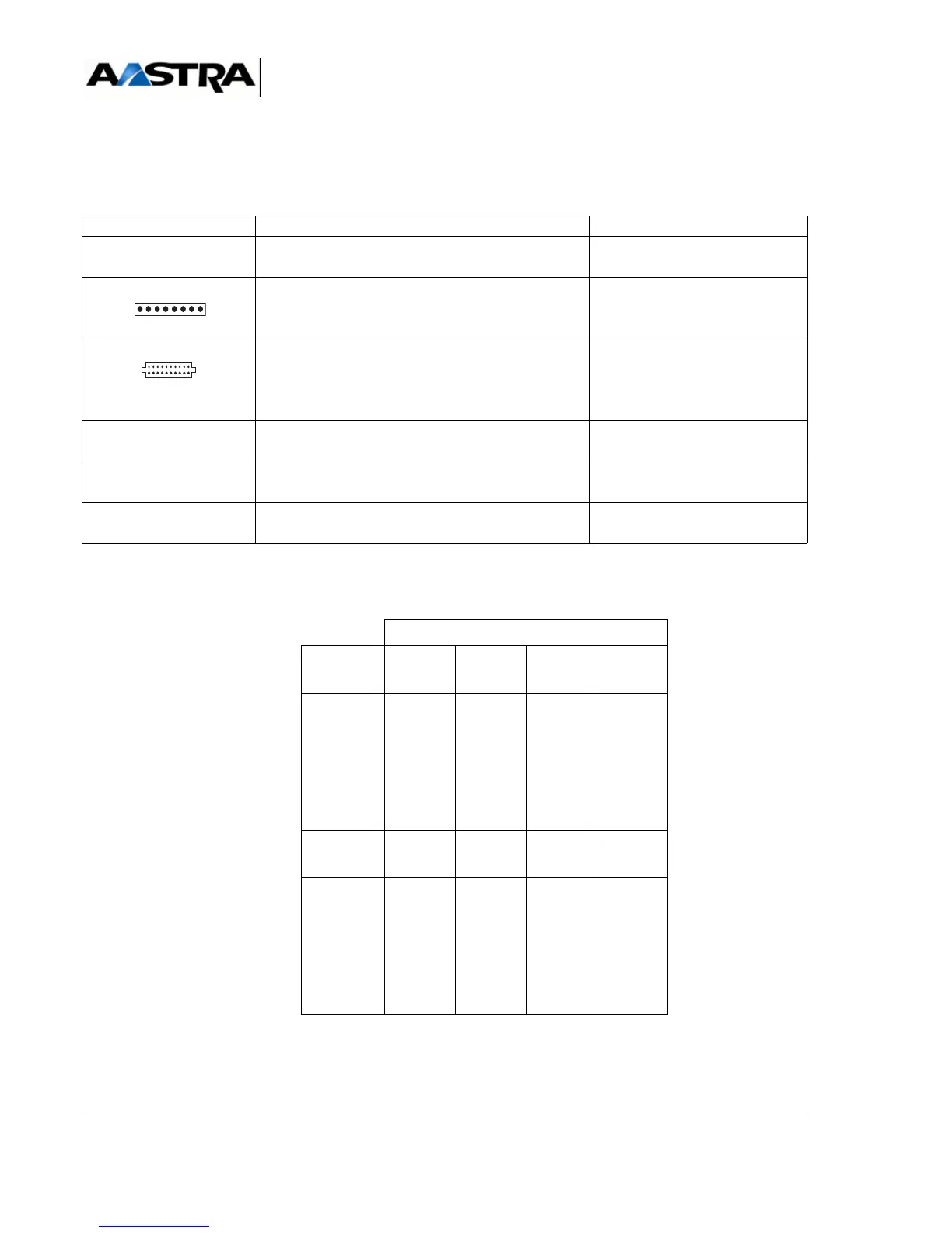
TABLEAU 4.39 DESCRIPTION OF LD4NX CARD CONNECTORS
Caution: The ISDN 40V voltage is supplied by the AXL iPBX backplane.
NAME FUNCTIONS/CHARACTERISTICS CONTACTS
J1 96-pin connector:
backplane connection.
J4 HE14 connector - 1 x 8 male pins: used for
loading programmable components "On Site"
(reserved for manufacturer).
not used
J5 and J6 Two connectors AMP CMS 2 x 10 female pins:
hosts an ADPCM16V daughter card.
Caution: the ADPCM8V daughter card is not
managed by the LD4N/LD4X card.
console RJ45 -8 pin connectors: debug console, reserved
for manufacturer.
S0 to S3 RJ45 -8 pin connectors:
connection to S0 interface.
(1)
T0 to T3 RJ45 -8 pin connectors:
connection to T0 interface.
(1)
LINE NO.
Pin No. T3 T2
(PRI)
T1 T0
(BRI)
1
2
3
4
5
6
7
8
ED3
RD3
NRD3
NED3
ED2
RD2
NRD2
NED2
ED1
RD1
NRD1
NED1
ED0
RD0
NRD0
NED0
Pin No. S3 PRI
(S2)
S1 S0
1
2
3
4
5
6
7
8
RD3
ED3
NED3
NRD3
RD2
ED2
NED2
NRD2
RD1
ED1
NED1
NRD1
RD0
ED0
NED0
NRD0