AMT/PTD/PBX/0058/4/6/EN Installation and Maintenance Manual - Aastra 5000
Page 246 01/2011 Description des sous-ensembles
Indicators: The indicators are located on the card circuit and not on the front panel.
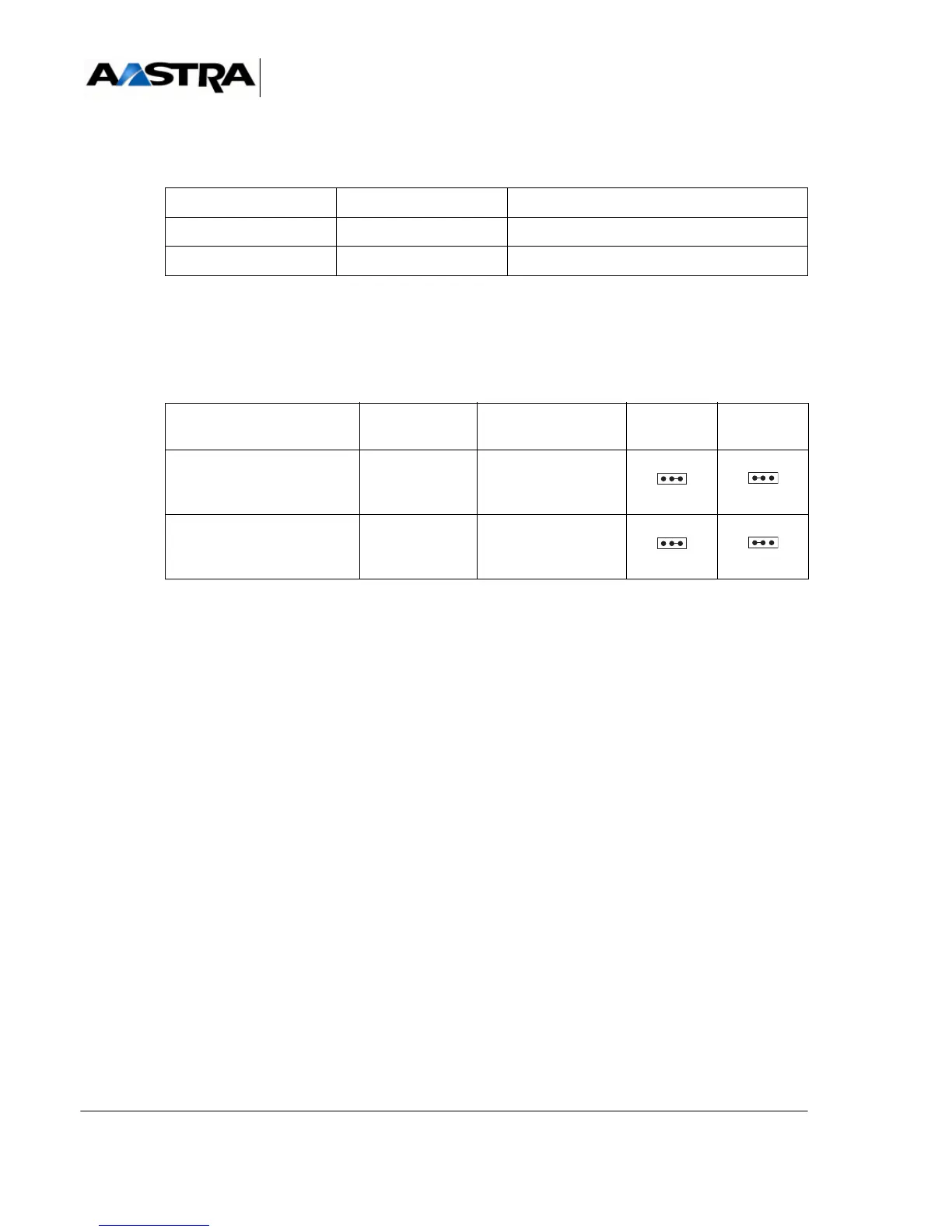
TABLEAU 4.57 PRESENTATION OF CS1 CARD INDICATORS
4.13.6.4 Hardware configuration
The SW1 and SW2 microswitches are used to select V10 or V28 mode.
TABLEAU 4.58 HARDWARE CONFIGURATION OF THE CS1 CARD
NAME STATE EXPLANATION
CR1 (red) On steady Incorrect operation
CR2 (red) Flashing rapidly Card in service
EQUIPMENT NUMBER CONNECTOR MICRO-
SWITCHES
V10 MODE V28 MODE
0J2SW1
1J3SW2