Installation and Maintenance Manual - Aastra 5000 AMT/PTD/PBX/0058/4/6/EN
Description des sous-ensembles 01/2011 Page 241
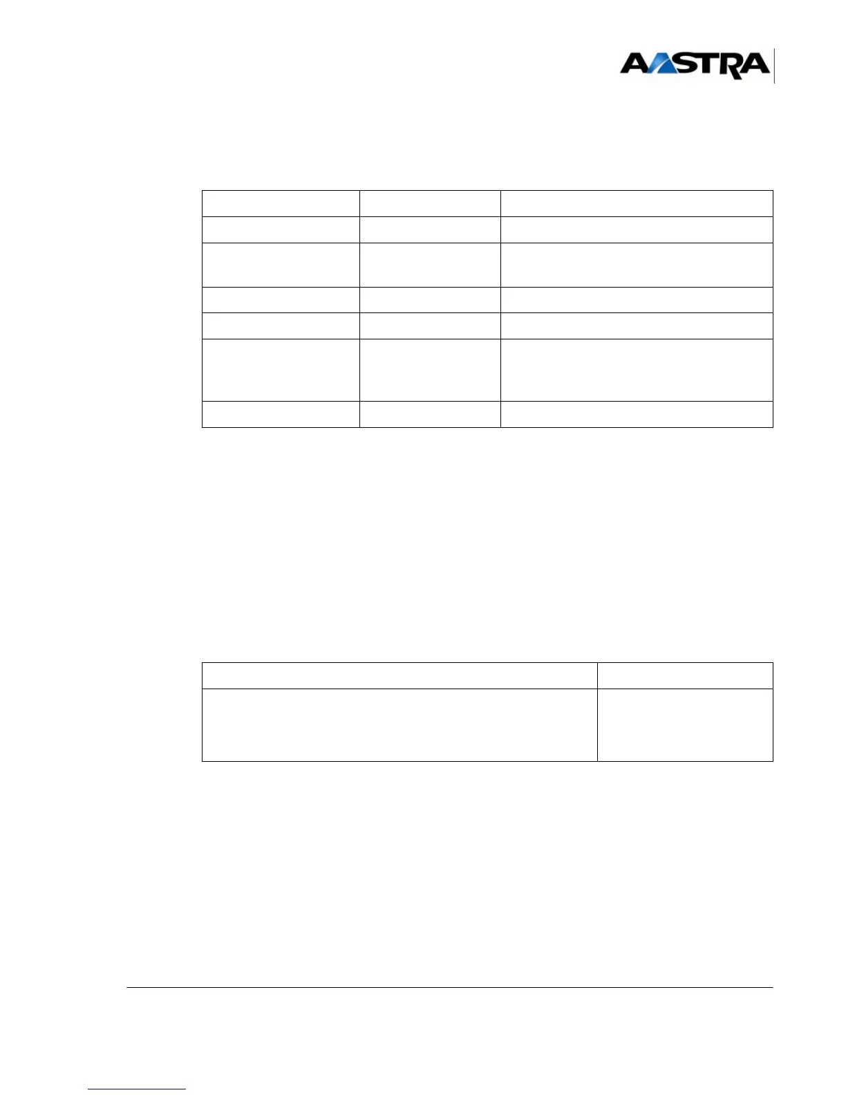
Indicators
The six LEDs described in the table below show the operating state of the card:
TABLEAU 4.53 PRESENTATION OF THE PT2 CARD INDICATORS
This VoIP card has no signalling indicator.
The front panel of the PT2 card includes:
• an "RST" push-button used to reset the card (manufacturer reserved),
• an "NMI" push-button used for an non maskable interruption of the processor
(manufacturer reserved).
4.13.5.4 Hardware configuration
The PT2 card has a CA1 configuration microswitch.
(1) Factory delivery configuration in bold characters
TABLEAU 4.54 HARDWARE CONFIGURATION OF THE PT2 CARD
INDICATOR STATE EXPLANATION
COL (green) On Ethernet collision
LINK (green) On
Status of the Ethernet link:
Good link with the Ethernet switch
TX (green) On LAN transmitting
RX (green) On LAN receiving
RUN (green) Flashing slowly
Flashing rapidly
Card downloading status:
Loading software
Card in operation
NRA (red) On Internal failure detected
DESIGNATION CONFIGURATION (1)
Operating mode:
• normal mode
• programming mode (programming the flash memory
using the
programming tool card)
CA1 on OFF
CA1 on ON