AMT/PTD/PBX/0058/4/6/EN Installation and Maintenance Manual - Aastra 5000
Page 240 01/2011 Description des sous-ensembles
4.13.5.3 Physical description (see Figure 4.44 )
Connectors
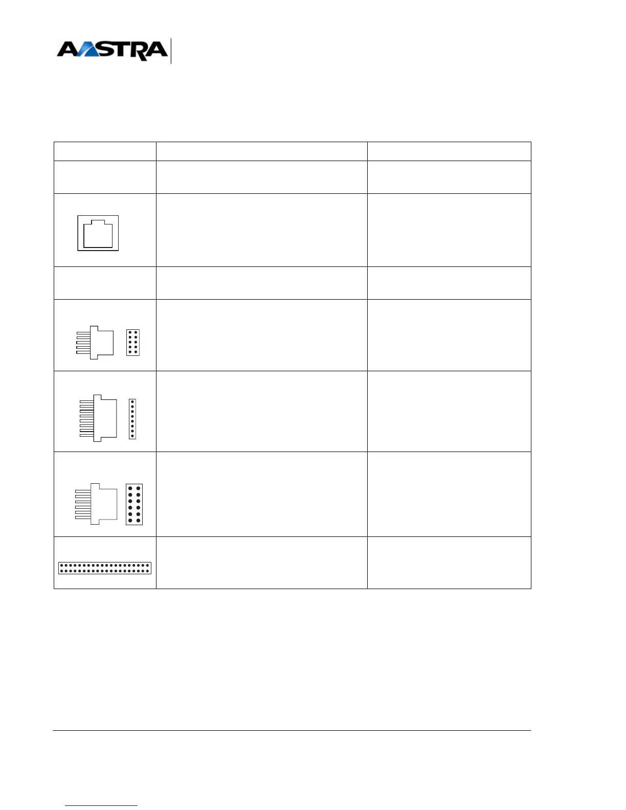
TABLEAU 4.52 DESCRIPTION OF PT2 CARD CONNECTORS
NAME FUNCTION/CHARACTERISTIC CONTACTS
J1 96-pin connector:
backplane connection.
10/100-TX LAN RJ45 connector:
An RJ45 connector can be used to connect a
LAN port compatible with the 10 Base T or 100
Base TX standards and compliant with IEEE
specification 802.
Pin 1: TPTX+
Pin 2: TPTX-
Pin 3: TPRX+
Pin 6: TPRX-
Pins 4, 5, 7, and 8: NC
console RJ45 connector:
reserved for the manufacturer.
J3 HE14 2 x 5-pin connector:
connecting a debug console
not used
J4 HE14 connector 1 x 8 pins:
loading programmable components "on site"
not used
J5 HE14 connector 2 x 6 pins:
connecting an emulator or a JTAG test tool
(debug)
not used
J6 and J7 2 x 40 pin and 2 x 20 pin connectors: location of
the VOIP4E daughter card.