AMT/PTD/PBX/0058/4/6/EN Installation and Maintenance Manual - Aastra 5000
Page 286 01/2011 Description des sous-ensembles
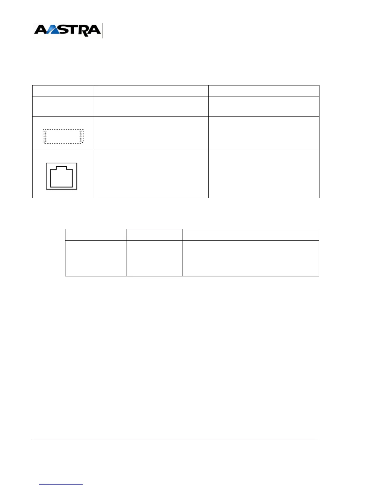
4.14.13.3Physical description (see Figure 4.62 )
Connectors
TABLEAU 4.79 DESCRIPTION OF THE LR4 CARD CONNECTORS
Indicators : The indicators are located on the card circuit and not on the front panel.
(1) x: INDICATOR number, each INDICATOR is assigned to a network line
TABLEAU 4.80 PRESENTATION OF THE LR4 CARD INDICATORS
NAME FUNCTION/CHARACTERISTIC CONTACTS
J1 96-pin connector:
backplane connection.
J4 to J11 Couples of connectors used for fitting the
DTOC, FTXA or FTXC daughter cards,
one card per analogue line
L0 to L3 RJ45 connectors:
each socket provides one connection to an
analogue network line
• Pin 4: network line (i)+
• Pin 5: network line (i)-
• Pins 1, 2, 3, 6, 7, and 8: NC
INDICATOR STATE EXPLANATION
D1.x (green) (1) Off
On
Flashing
Status of line x (1) :
• Line idle
• Line used
• Pulse dialling rate