Installation and Maintenance Manual - Aastra 5000 AMT/PTD/PBX/0058/4/6/EN
Description des sous-ensembles 01/2011 Page 287
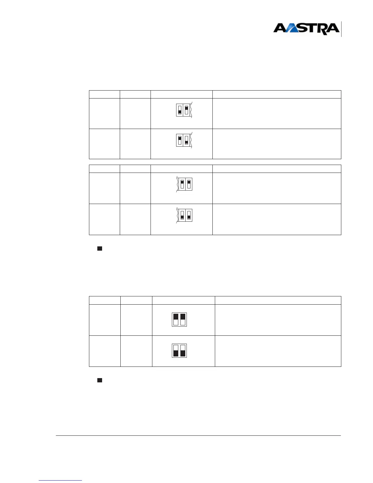
4.14.13.4Hardware configuration
Four “S1” micro-switches are used to configure the line balance and type of gain for each
standard network line (LS) or short network line (LC).
* Represents the microswitch.
(1) “x” represents the microswitch number (1 to 4).
TABLEAU 4.81 CONFIGURATION OF THE S1 MICROSWITCH ON THE LR4 CARD
Two “S2” microswitches are used to configure the billing frequency on a card fitted with
FTXC daughter cards.
* Represents the microswitch.
TABLEAU 4.82 CONFIGURATION OF THE S2 MICROSWITCH ON THE LR4 CARD
S1.X.1 S1.X.2 SWITCH LINE IMPEDANCE
OFF ON Complex impedance (factory setting)
ON OFF Impedance 600
Ω
S1.X.3 S1.X.4 SWITCH GAIN
ON ON Standard line gain, usable for 1.5 to 3.5 km
(factory setting)
OFF OFF Short line gain, usable for 0 to 1.5 km
S2.1 S2.2 SWITCH CHARGING FREQUENCY
OFF OFF 12 kHz
ON ON 16 kHz