Installation and Maintenance Manual - Aastra 5000 AMT/PTD/PBX/0058/4/6/EN
Description des sous-ensembles 01/2011 Page 277
4.14.9.3 Physical description (see Figure 4.58 )
Connectors
TABLEAU 4.76 DESCRIPTION OF THE LM8 CARD CONNECTORS
Indicators
This card has no signalling indicator.
4.14.9.4 Hardware configuration
The LM8 card has no configuration microswitch.
4.14.9.5 Installation and wiring
The LM8 card cannot be hot-plugged in a working AXD and AXL iPBX. The iPBX must be
powered off before inserting the card. An LM8 card cannot be plugged into AXD and AXL
expansion cabinets either.
The constraints for wiring are those relating to connection with analogue sets
(see Section4.14.1.5) and digital sets (see Section4.14.5.5).
The minimum diameter of the cables has to be 26AWG (0.4mm).
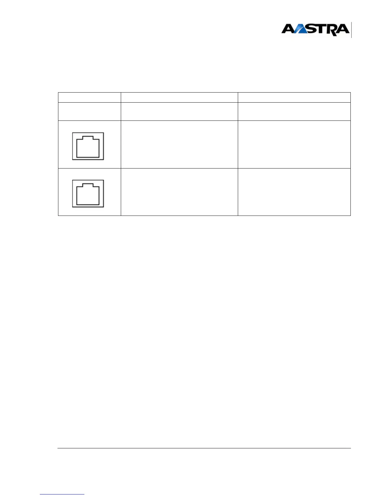
NAME FUNCTION/CHARACTERISTIC CONTACTS
J1 96-pin connector:
backplane connection.
A0 to A3 RJ45 connectors:
each socket provides one connection to an
analogue set
• Pin 4: analogue set (i)+
• Pin 5: analogue set (i)-
• Pins 1, 2, 3, 6, 7, and 8: NC
N4 to N7 RJ45 connectors:
each socket provides one connection to a
digital set
• Pin 4: digital set (i)+
• Pin 5: digital set (i)-
• Pins 1, 2, 3, 6, 7, and 8: NC