Installation and Maintenance Manual - Aastra 5000 AMT/PTD/PBX/0058/4/6/EN
Description des sous-ensembles 01/2011 Page 291
Information can be transmitted:
• either using RON/TRON signals,
• or an alternate current. The card has a 50 Hz current generator for this purpose,
• Power supply: the LI1 card receives several supply voltages on the backplane
connector (J1):
- +5 V, -5 V used for the operation of its internal circuits,
- -48 V used for the operation of its internal circuits.
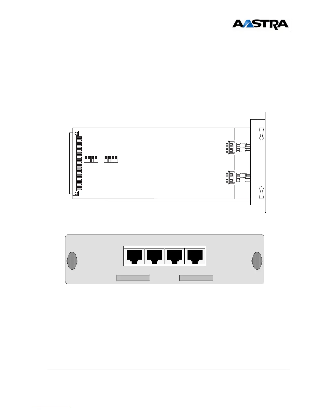
Figure 4.63 O
VERVIEW OF THE LI1 CARD