Installation and Maintenance Manual - Aastra 5000 AMT/PTD/PBX/0058/4/6/EN
Description des sous-ensembles 01/2011 Page 299
4.14.15.3Physical description (see Figure 4.50 )
Connectors
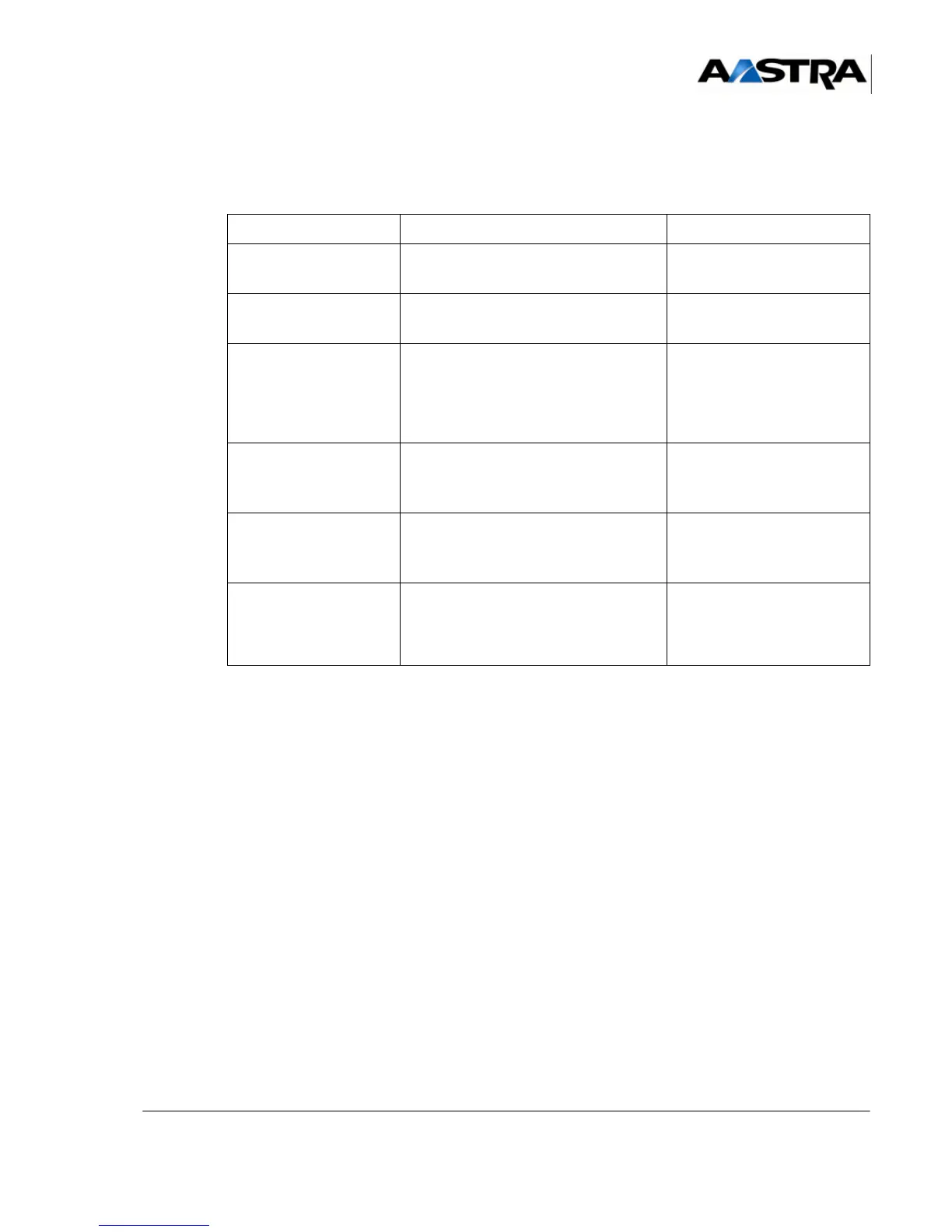
TABLEAU 4.87 DESCRIPTION OF THE BTX CARD CONNECTORS
NAME FUNCTION/CHARACTERISTIC CONTACTS
J1 96-pin connector:
Backplane connection
J8 Stocko 3-pin connector:
External buffer power supply
•Pin 1: GND
•Pin 3: +12 V
PRN
RJ45 connector:
connection to a PC or printer
•Pin 1: TX
•Pin 2: RX
• Pins 3,4,5 and 6: GND
•Pin 7: CTS
•Pin 8: RTS
CHARGE
RJ45 connector:
link with printer port on UCV card
(ticket serial port)
•Pin 1: RD
• Pins 3,4,5 and 6: GND
•Pin 7: DTR
MMI
RJ45 connector:
link with operating port on UCV card
(MMC serial port, optional)
•Pin 1: TD
•Pin 2: RD
• Pins 3,4,5 and 6: GND
ALA
RJ45 connector:
relay contact
• Pin 1: Line B
• Pin 2: Line B
• Pin 3: not used
• Pin 4: not used