Installation and Maintenance Manual - Aastra 5000 AMT/PTD/PBX/0058/4/6/EN
Description des sous-ensembles 01/2011 Page 187
4.8.2.2 Indicators
The EXT1-S card does not have any indicators on the front panel.
4.8.3 Hardware and software configuration
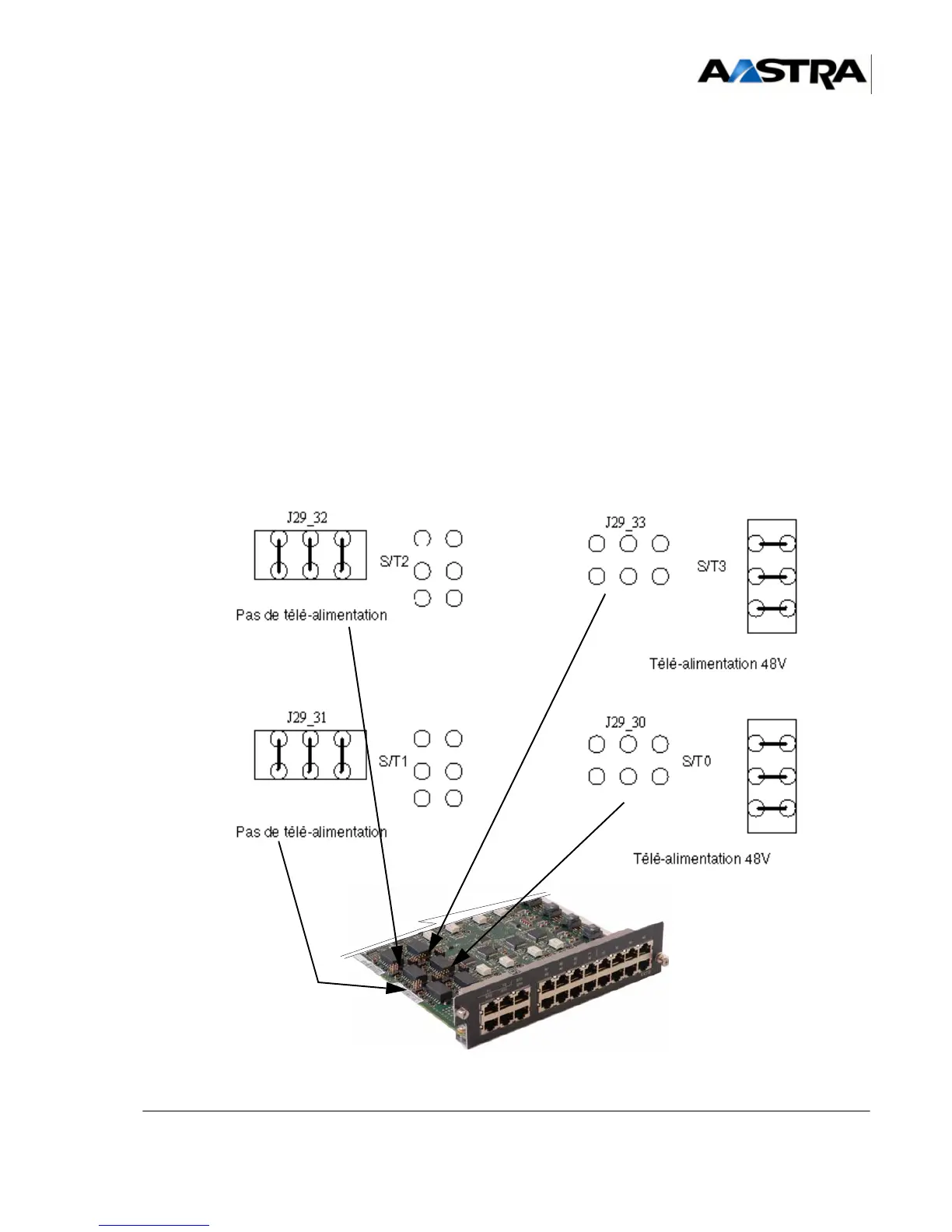
The EXT1-S card has 4 jumpers for configuring remote power supply of the S/T0 to S/T3
accesses (one jumper block for each access). These jumpers are fitted on connectors
J29_xx and J30_xx located on the front panel of the EXT1-S card (J29_30 for S/T0
access, J29_31 and J30_31 for S/T1 access).
The four accesses are placed vertically on the card. The one at the bottom is the S/T0
access and the one at the top the S/T3 access.
Depending on the position of the jumpers, the S/T0 to S/T3 accesses will be configured
as follows:
• No remote power supply.
• Remote supply of - 48 V.
Figure 4.25 C
ONFIGURING REMOTE POWER SUPPLY OF S/T0 TO S/T3 ACCESSES