AMT/PTD/PBX/0058/4/6/EN Installation and Maintenance Manual - Aastra 5000
Page 168 01/2011 Description des sous-ensembles
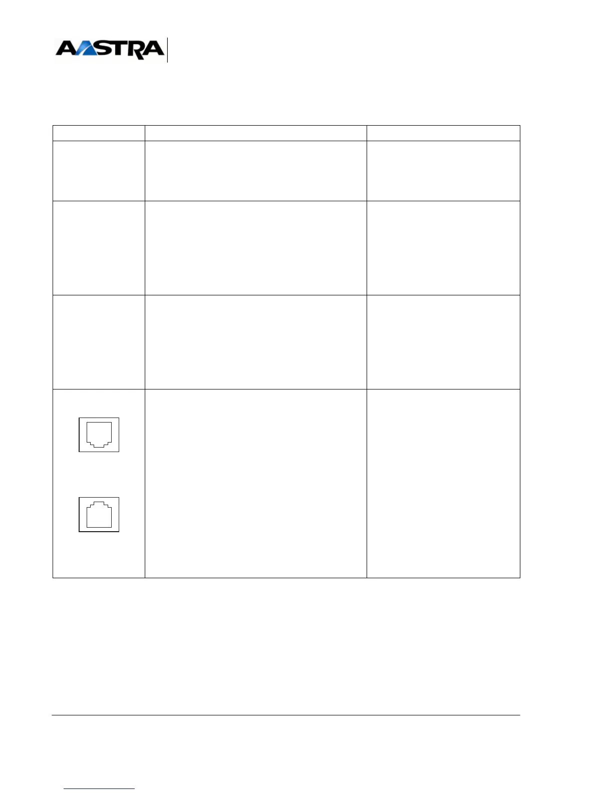
(1) Connector front view
TABLEAU 4.14 DESCRIPTION OF UCV-L CARD CONNECTORS (2/3)
NAME FUNCTIONS/CHARACTERISTICS CONTACTS
USB (B)
(1)
USB connector in DEVICE mode • Pin 1: NC
• Pin 2: DNEG2
• Pin 3: DPOS2
• Pin 4: User ID
• Pin 5: GND
ETH1
(1)
RJ45 connector • Pin 1: RXP
• Pin 2: RXM
•Pin 3: TXP
•Pin 4: TLBR
•Pin 5: TLBR
•Pin 6: TXM
• Pin 7: RLBR
• Pin 8: RLBR
ETH2
(1)
RJ45 connector:Connection used for the access
Administration in the case of configuration of
separation of the networks Administration and
Telephony.
(refer to Manual AMT/PTD/PBX/0101).
• Pin 1: RXP
• Pin 2: RXM
•Pin 3: TXP
•Pin 4: TLBR
•Pin 5: TLBR
•Pin 6: TXM
• Pin 7: RLBR
• Pin 8: RLBR
DECT SYNC P
(1)
DECT SYNC S
(1)
RJ45 double connector: primary and secondary
DECT synchronisation ports, for radio base stations
DECT SYNC P :
• Pin 1: AHGA
• Pin 2: AHGB
• Pin 3: NHBIT1
• Pin 4: NHDECT1
• Pin 5: PHDECT1
• Pin 6: PHBIT1
• Pin 7: HEXTA
• Pin 8: HEXTB
DECT SYNC S :
• Pin 1 and 2: L0V
• Pin 3: NHBIT2
• Pin 4: NHDECT2
• Pin 5: PHDECT2
• Pin 6: PHBIT2
•Pins7and8: L0V