Installation and Maintenance Manual - Aastra 5000 AMT/PTD/PBX/0058/4/6/EN
Description des sous-ensembles 01/2011 Page 179
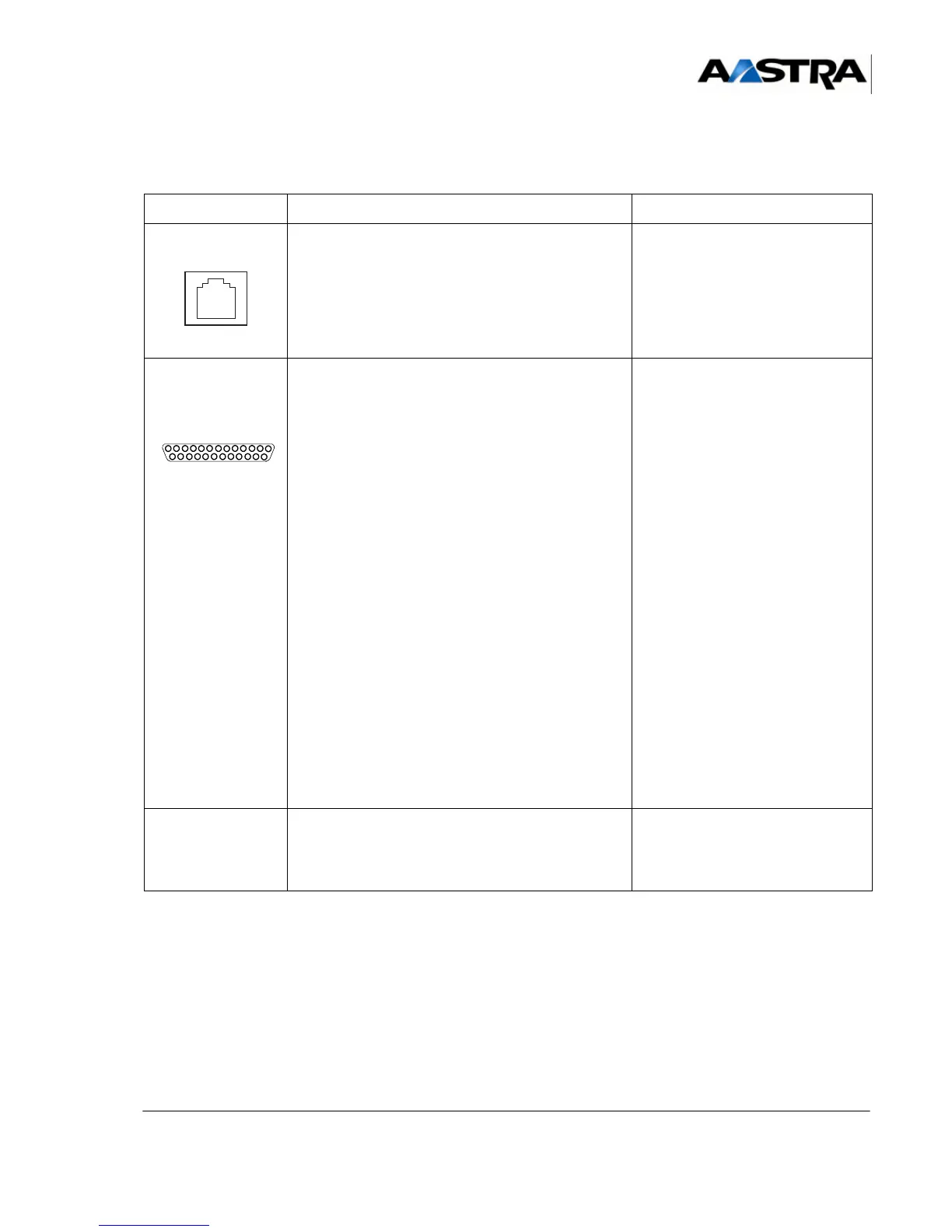
(1) Connector front view.
(2) Tableau 4.16 and Figure 4.20 give the details relating to the command relays.
TABLEAU 4.20 DESCRIPTION OF UCV-S CARD CONNECTORS (3/3)
NAME FUNCTION/CHARACTERISTIC CONTACTS
MUSIC
(1)
RJ45 8-pin connector: hosts an external source of
music-on-hold.
MUSA: Input impedance 15 Kohms.
MUSB: Input impedance 600 Kohms.
ETM: external source present.
•Pin 2: JP12
• Pin 3: GNDL
•Pin 4: MUSA
•Pin 5: ETM
• Pin 6: GNDL
•Pin 7: MUSB
• Pins 1 and 8: NC
ALARM / REMOTE
CONTROL
(1)
DB25-F connector: hosts the alarms and relays
connection:
• includes four alarm inputs controlled by a TTL
electric level, used for the built-in UAD function.
• 4 command relays (2).
• Pin 1: NAL[3]
(alarm input 3)
• Pin 2: GND NAL[3]
(alarm input 2)
• Pin 3: NAL[2]
(alarm input 1)
• Pin 4: GND NAL[2]
(alarm input 0)
• Pin 5: NAL[1]
• Pin 6: GND NAL[1]
• Pin 7: NAL[0]
• Pin 8: GND NAL[0]
•Pin 9: R4B
• Pin 10: R4A
• Pin 11: R3B
• Pin 12: R3A
• Pin 13: R2C
• Pin 14: R2B
• Pin 15: R2A
• Pin 16: R1B
• Pin 17: R1A
• Pin 18: JP12 (+ 12 V)
• Pin 19: GNDL
• Pin 19: R2B
• Pins21to25: NC
UART Debug HE14 connector. • Pin 1: TXA
•Pin 2: GND
•Pin 3: RXA
•Pin 4: GND