Installation and Maintenance Manual - Aastra 5000 AMT/PTD/PBX/0058/4/6/EN
Description des sous-ensembles 01/2011 Page 211
TABLEAU 4.33 DESCRIPTION OF LD4 CARD CONNECTORS
(1) See the detail of the connections in Tableau 4.34 .
TABLEAU 4.34 DETAILS OF THE S0/T0 CONNECTIONS OF LD4 CARD
CONNECTORS
Indicators:The indicators are located on the card circuit and not on the front panel.
TABLEAU 4.35 PRESENTATION OF THE LD4 CARD INDICATORS
console RJ45 -8 pin connectors: reserved for the
manufacturer.
S0 to S2 RJ45 -8 pin connectors:
connection to S0 interface.
(1)
S3 RJ45 -8 pin connector: connection to S0 interface
+ ISDN 40 V remote supply voltage.
(1)
T0 to T2 RJ45 -8 pin connectors:
connection to T0 interface.
(1)
T3 RJ45 -8 pin connector:
connection to T0 interface + 40 V ISDN remote
supply voltage(1).
(1)
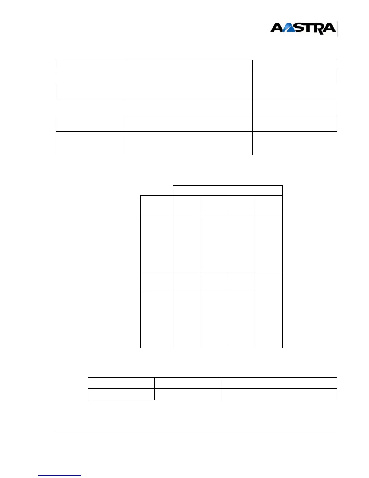
LINE NO.
Pin No. T3 T2
(PRI)
T1 T0
(BRI)
1
2
3
4
5
6
7
8
M40 V
ED3
RD3
NRD3
NED3
P40 V
ED2
RD2
NRD2
NED2
ED1
RD1
NRD1
NED1
ED0
RD0
NRD0
NED0
Pin No. S3 PRI
(S2)
S1 S0
1
2
3
4
5
6
7
8
M40 V
RD3
ED3
NED3
NRD3
P40 V
RD2
ED2
NED2
NRD2
RD1
ED1
NED1
NRD1
RD0
ED0
NED0
NRD0
NAME STATE EXPLANATION
CR2 (red) Flashing rapidly Card in service
NAME FUNCTIONS/CHARACTERISTICS CONTACTS