AMT/PTD/PBX/0058/4/6/EN Installation and Maintenance Manual - Aastra 5000
Page 248 01/2011 Description des sous-ensembles
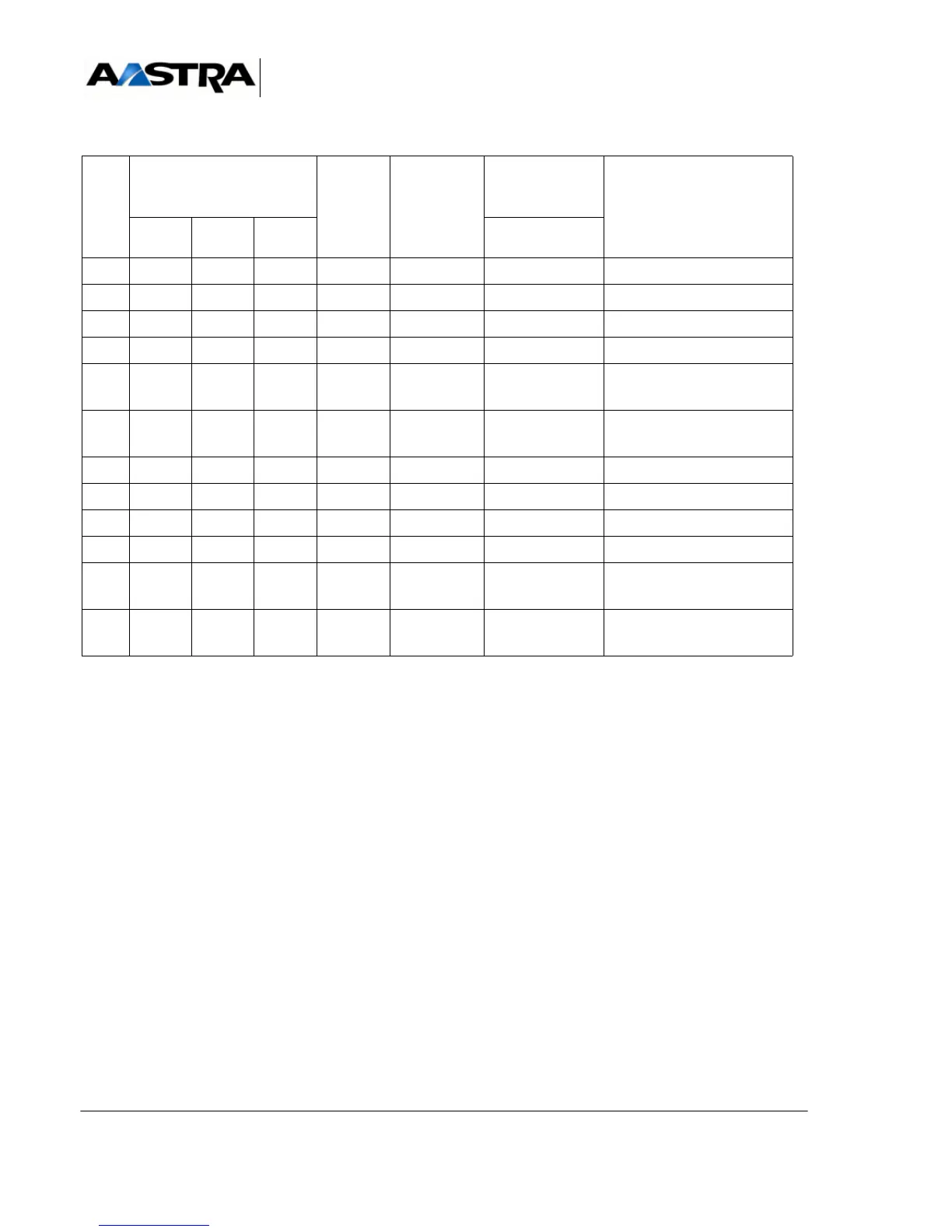
TABLEAU 4.60 CONNECTING A DTE (CS1) TO A DCE
CIRC
T
V24 SIGNAL NAME DCE
ISO 2110
(25 PINS)
DIRECTION
CS1-->DCE
CS1 CARD
CONNECTORS
FUNCTION
CCITT: EIA CS1
Port1/Port 2
104 RD RD NDE 3 <--- 3 Received data
103 ED ST/TD NDR 2 ---> 2 Transmitted data
108 TDP DTR DTR 20 ---> 5 card present output
106 PAE CTS CTS 5 <--- 4 flow control input
102 TS GND SGND 7 ---> 7 0 V return for junction
outputs
115 HRM CR HR 17 <---- 24 clock received for received
data
113 XTC 24 ---> 15 clock signal sent
not wired
105 DPE RTS RTS 4 ---> 20 flow control output
109 DS CD CD 8 <--- 8 terminal present input
RET 7 ---> 0 V for junction input (with
V10)
114 HEM TC HT 15 <---- 17 clock received for data
transmitted