Installation and Maintenance Manual - Aastra 5000 AMT/PTD/PBX/0058/4/6/EN
Maintenance 01/2011 Page 413
PROCEDURE
See Figure 4.5 for an overview of the power supply module.
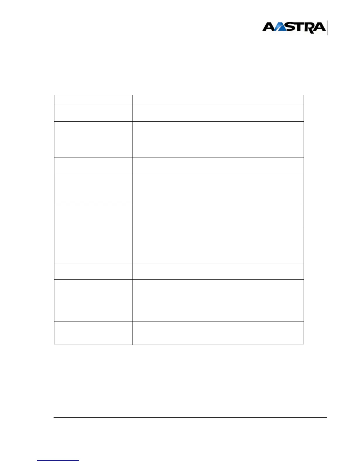
Table 2:
OPERATION DETAILS OF THE OPERATION / COMMENTS
• Alert the operator. • In the case of remote operation, contact the remote operator
before starting any operation.
• Power off the power
supply module to be
removed.
• Refer to Section 6.4, Stopping the system (AXD, AXL, AXS,
AXS12 and AXS6)Error! No bookmark name given.
• If it is the power supply module of a main cabinet in an iPBX with
multiple cabinets, also power off the power supply module of the
expansion cabinets ("I/O" switch on "O").
• Disconnect the cables. • Disconnect the mains cable, and if required the backup battery
connected on the front panel of the power supply module.
• Pull out the power supply
module.
• Unscrew the two securing screws on the front panel of the power
supply module.
• Pull out the power supply module using its handles, and remove
it.
• Check the functional
technical state of the new
power supply module.
• Check that the functional technical state of the new power supply
module is compatible with the old one.
• Fit the new power supply
module.
• Check that the new power supply module is powered off (“I/O”
switch set to “O”).
• Insert the power supply module in its slot and push it fully home.
• Secure the power supply module onto the iPBX structure using
its two captive screws.
• Connect the cables. • Connect the mains cable, and if required the backup battery
connected on the front panel of the power supply module.
• Power on the power
supply module.
• "I/O" switch on "I".
• If it is the power supply module of the main cabinet in an iPBX
with multiple cabinets:
- first power on the power supply modules in the expansion
cabinets,
- then power on the power supply module in the main cabinet.
• Check the status of the
indicators on the front
panel.
Refer to Section 4, Description des sous-ensemblesError! No
bookmark name given.