28 Program features
The reactive power control curve activates when the lock-in condition set by parameter
124.31 Lock-in level is exceeded and deactivates when lock-out condition set by
parameter124.32 Lock-out level is deceeded. In Q(U) control curve, the conditions are
percent of active power. In other curves the conditions are percent of nominal voltage. The
lock-in condition can be set so that the curves are always active (set to zero (power > 0 or
voltage > 0)).
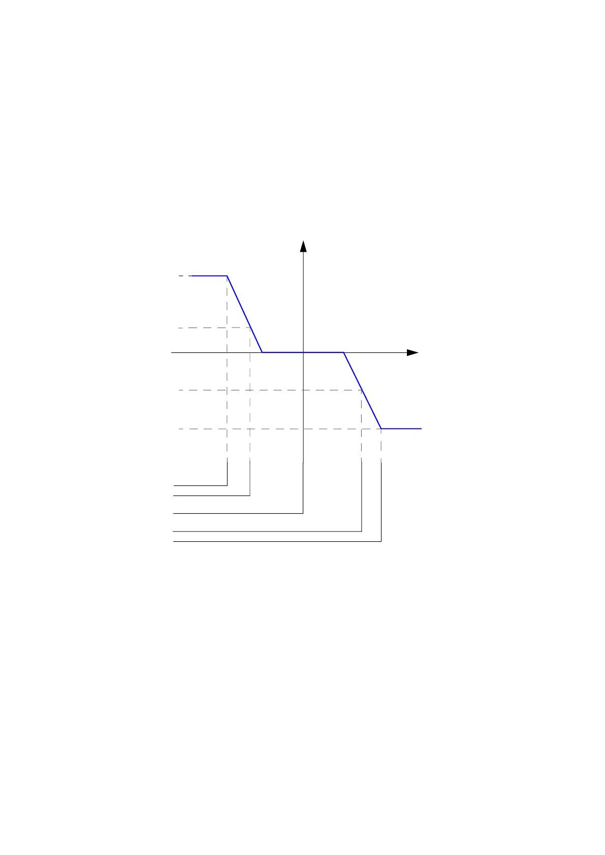
Q(U) control curve
In Q(U) control curve mode, reactive power generated by the inverter depends on the grid
voltage as described in the example Q(U) control curve. Active power in percent is used as
a lock-in and lock-out conditions.
Figure 8. Q(U) control curve
The delay time for activating the Q(U) regulation curve can be set in parameter124.45
Q(U) activation delay. The lower limit for nominal voltage activation can be set with
parameter124.46 Q(U) activation level low. When grid voltage falls below this limit, the
curve is active. The upper limit for nominal voltage activation can be set with parameter
124.47 Q(U) activation level high. When grid voltage goes beyond this limit, the curve is
active.
U
Q
Q(U) is selected when:
Input = grid AC voltage
Output = reactive power reference
124.39 Q(x) output level 1
124.40 Q(x) output level 2
124.41 Q(x) output level 3
124.42 Q(x) output level 4
124.43 Q(x) output level 5
124.44 Q(x) output level 6
124.33 Q(x) input level 1
124.34 Q(x) input level 2
124.35 Q(x) input level 3
124.36 Q(x) input level 4
124.37 Q(x) input level 5
124.38 Q(x) input level 6