18 Program features
Connection limits
The grid monitoring function of the inverter includes a connection condition check that is
active when the inverter is attempting to connect to the grid. Typically, grid connection
limits are more stringent than grid disconnection limits. Connection limits may also be
referred to as "cut-in" conditions. There are connection limits for underfrequency,
overfrequency, overvoltage, and undervoltage. Each phase/main voltage is independently
monitored. The connection limits can be disabled, enabled only for the first connection, or
enabled also for reconnections.
Settings
Parameters:135.20...135.27
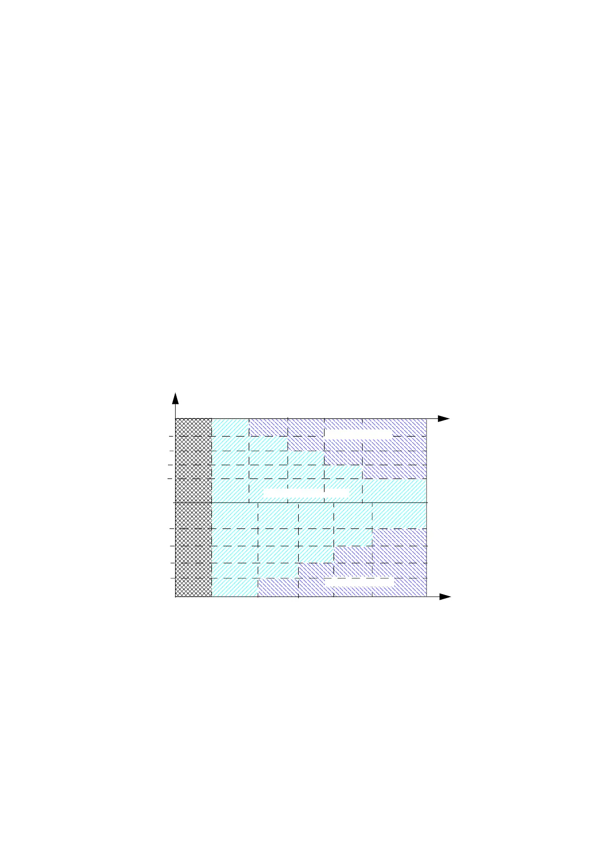
Voltage monitoring
There are four limits for undervoltage monitoring and four limits for overvoltage monitoring.
Each limit has an enable parameter, a limit parameter, and a time parameter.
When the limit is enabled and the measured value exceeds the limit for the duration of the
time parameter, the grid is declared as unstable. All limit checks are logically connected in
parallel. Each phase/main voltage is independently monitored.
Figure 2. Voltage monitoring timing diagram
Settings
Parameters: 135.50 Undervoltage enable 1...135.74 Overvoltage time 4
U (p.u)
t (s)
1.0
135.71 Overvoltage time 3
135.68 Overvoltage time 2
135.65 Overvoltage time 1
135.55 Undervoltage time 2
135.52 Undervoltage time 1
0
135.54 Undervoltage limit 2
135.67 Overvoltage limit 2
135.64 Overvoltage limit 1
135.51 Undervoltage limit 1
Inverter trip area
Inverter trip area
Normal operation area
135.58 Undervoltage time 3
135.70 Overvoltage limit 3
135.57 Undervoltage limit 3
t (s)
135.74 Overvoltage time 4
135.61 Undervoltage time 4
135.73 Overvoltage limit 4
135.60 Undervoltage limit 4