Program features 53
Tabel 5: Example of customer interface analog inputs configuration
Settings
177.51 Transformer temperature 1 source...177.73 Transformer temperature 2, current
limit current 2
Digital output
The only digital output for the MV station is the MV switchgear breaker opening signal.
This signal is controlled by different features of the MV transformer or by user control. The
MV breaker opening signal can be routed from the software to the physical IO by setting
the parameter 176.11 Relay output x20.8 source = MV breaker status [4].
For actual connections of digital output, refer to the Hardware manual.
Customer external faults
There are three user input sources that can be configured to trigger external faults for the
customer-related features using digital inputs:
• External fault 1 source
• External fault 2 source
• External fault 3 source
Any of these faults can be configured to use any of the customer-related external faults.
For details of the I/O connections, refer to the Hardware manual and Commissioning and
maintenance manual.
Each configured external fault has the following set of parameters:
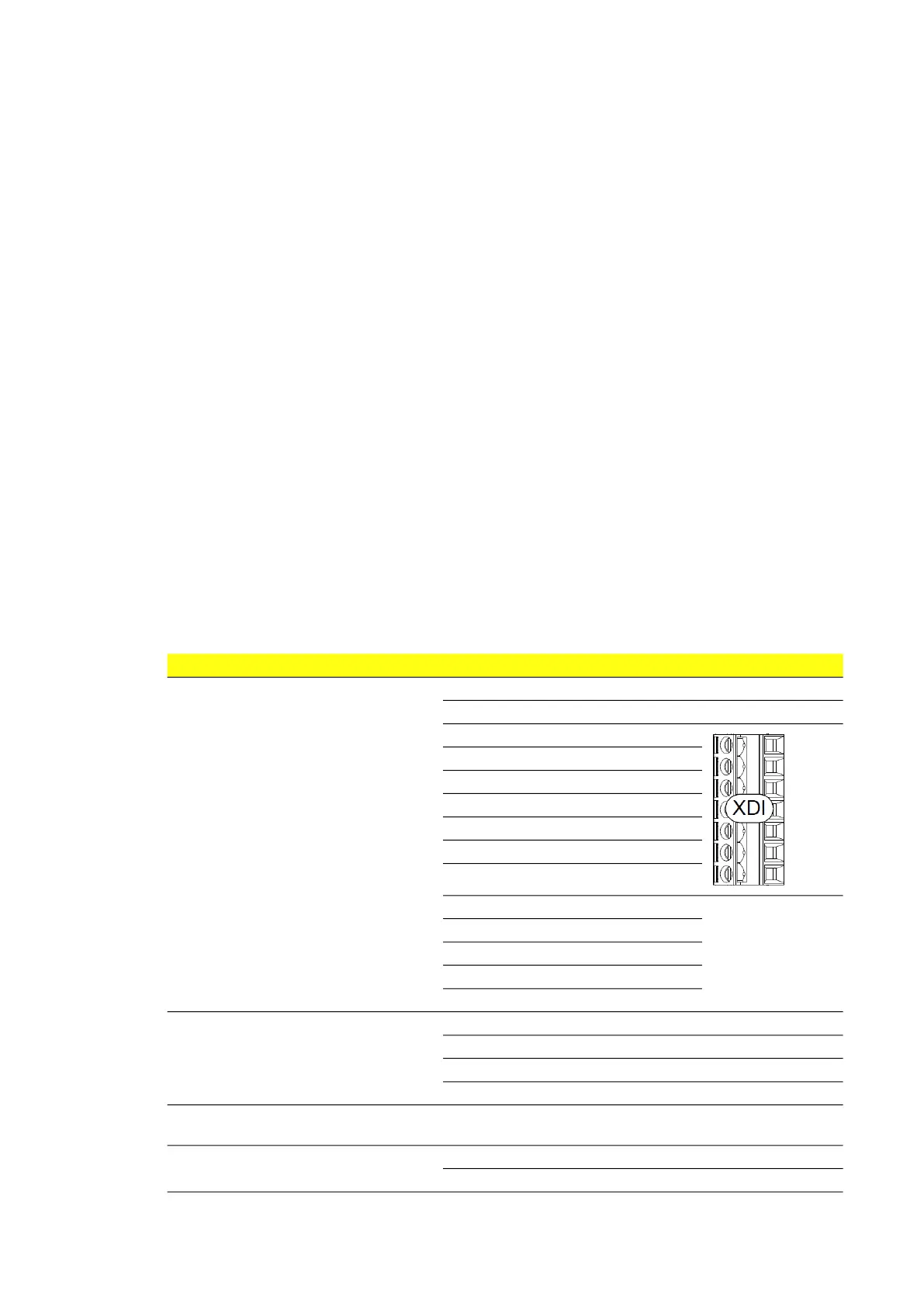
Parameter type Selection list 0X20 terminal
Source Off [0]
On [1]
Digital input X20.1 [2]
Digital input X20.2 [3]
Digital input X20.3 [4]
Digital input X20.4 [5]
Digital input X20.5 [6]
Digital input X20.6 [7]
Digital input X20.7 [8]
Spare DI8 [9] Not supported in this
release.
Spare DI9 [10]
Spare DI10 [11]
Spare DI11 [12]
Spare DI12 [13]
Action No action [0]
Delayed warning [1]
Warning and delayed fault [2]
Delayed fault [3]
Action delay Delay time to trigger the defined fault
action.
Failure logic Active low [0]
Active high [1]