Program features 21
External grid monitoring relay
Depending on the installation, an external third party-certified grid monitoring relay may be
used. If an external relay is used, loose limits for grid monitoring should be set. The
recommended setting for the overvoltage monitoring limit is 130%. The limit for
undervoltage monitoring should be set as less than the external relay setting.
The inverter can use external grid monitoring through the parameter 135.16 External trip
that can be written, e.g., by fieldbus. If this parameter has a value of 1, external grid
monitoring indicates an unstable grid.
Settings
Parameter:135.16 External trip
Fault ride-through tripping curve
The fault ride-through (FRT) tripping curve function is an extra undervoltage and
overvoltage tripping function. The function programs a curve where the inverter
disconnects from the grid. The grid codes define the inverter behavior during a grid fault.
Typically, they specify the following:
• how long a dip can last for
• how long a swell can last for
• how to behave with symmetrical voltage dips and peaks
• how to behave with asymmetrical voltage dips and peaks.
There are two different cases of FRT function:
• Low-voltage ride-through (LVRT), see page 21 and
• High-voltage ride-through (HVRT), see page 22.
The FRT function can be enabled with parameter 126.01 FRT enable.
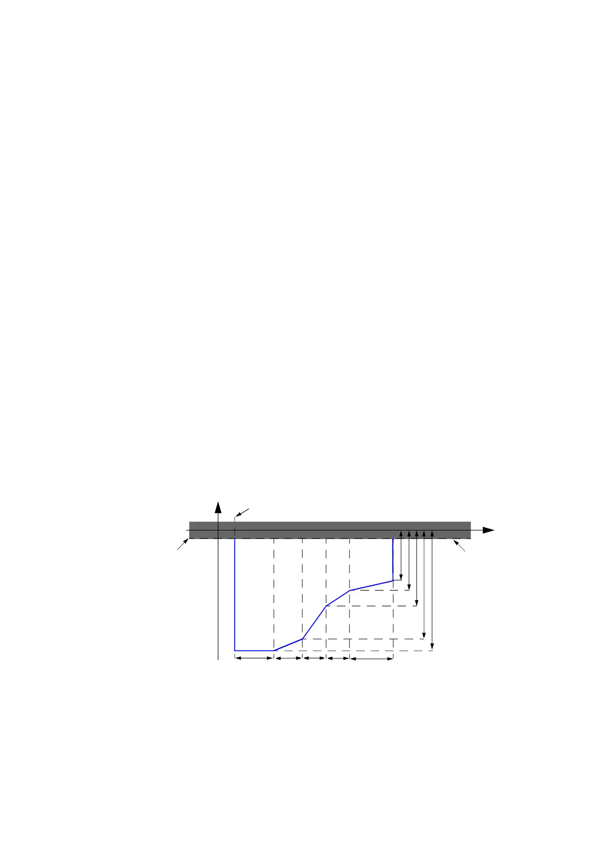
Low-voltage ride-through (LVRT) tripping curve
Figure 4. Low-voltage ride-through (LVRT) tripping curve
If the grid voltage drops below the low-voltage ride-through triggering level defined by
parameter 126.10 Lv Rt trig U %, the inverter indicates a grid warning. If the grid transient
lasts longer than the voltage dependent time defined by parameters 126.12 Lv Rt sec 1
time...126.28 Lv Rt ext U %, the inverter trips. Otherwise the inverter operates normally
without interruptions after the LVRT event has ended.
U
Section durations
Starting and final voltage
levels for different sections
U
n
126.10 Lv Rt trig U %
Normal operating area
LVRT event starting point
sec1 sec2 sec3 sec4 sec5