22 Program features
After the LVRT event, the MPPT of the inverter starts generating power according to the
voltage level present. A fast recovery function can be enabled with parameter 178.03 Fast
recovery. This enables a rapid recovery of the DC link voltage from the open circuit voltage
to the voltage that was present before the LVRT. The ramp for the function can be set with
parameter 178.41 Recovery ramp. These parameters are set by the grid code.
The LVRT tripping curve is defined using five temporal sections. Each section is
parametrically defined by duration, starting, and final voltage level. These parameters exist
in the parameter group 126 FRT tripping curve. The Low-voltage ride-through (LVRT)
tripping curve shows an example of the LVRT tripping curve. When the voltage remains
above the line defined by the five sections, the inverter stays connected to the grid;
otherwise the inverter stops operation.
The voltage comparisons are defined using parameters 126.02 Lv Rt symm sig...126.03
Lv Rt asymm sig. The asymmetric limit can be set with parameter 126.06 Asymm/symm
limit.
Note: Consider the grid monitoring settings when defining LVRT settings.
Settings
See parameter groups: 126 FRT tripping curve, 178 MPPT settings
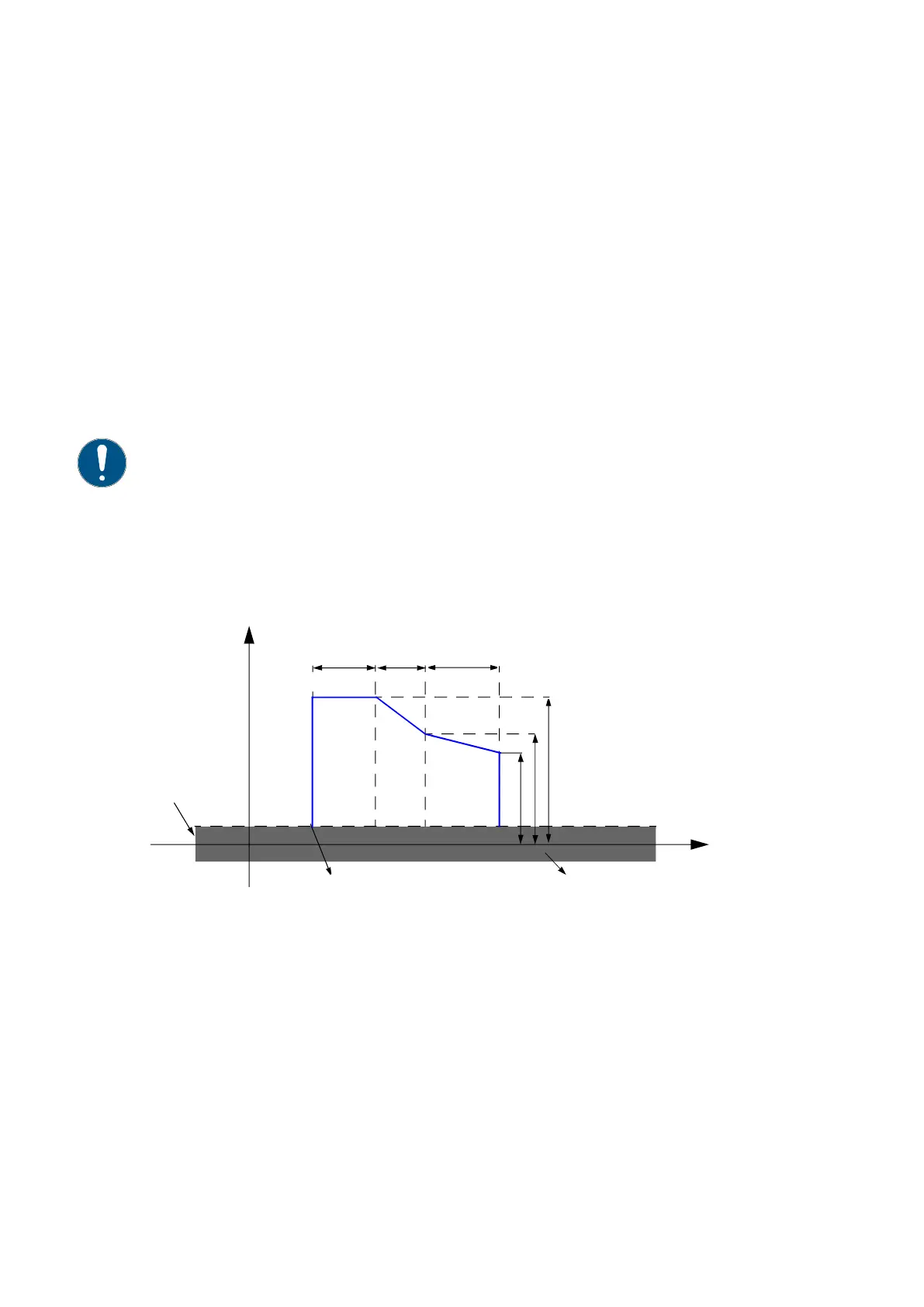
High-voltage ride-through (HVRT) tripping curve
Figure 5. High-voltage ride-through (HVRT) tripping curve
If the grid voltage rises above the high-voltage ride-through (HVRT) triggering level
defined by parameter 126.30 Hv Rt trig U %, the inverter indicates a grid warning. If the
grid transient lasts longer than the voltage dependent time defined by parameters 126.32
Hv Rt sec 1 time...126.42 Hv Rt S3 end U %, the inverter trips. Otherwise the inverter
operates normally without interruptions after the HVRT event has ended.
The HVRT tripping curve is defined using three temporal sections. Each section is
parametrically defined by duration, starting, and final voltage level (See group 126 FRT
tripping curve). The High-voltage ride-through (HVRT) tripping curve shows an example of
the HVRT tripping curve. When the voltage remains below the line defined by the three
sections, the inverter stays connected to the grid; otherwise the inverter stops operation.
U
Section durations
HVRT event starting point
Normal operating area
t
Un
Starting and final voltage
levels for different sections
126.30 Hv Rt trig U %
sec1 sec2 sec3