Rotor (power) angle δ can be thought of as the angle between the two lines,
connecting point 0 in Figure 61, that is, Z(R, X) under normal load, with the points
SE and RE, respectively. These two lines are not shown in Figure 61. Normal
values of the power angle, that is, under stable, steady-state, load conditions, are
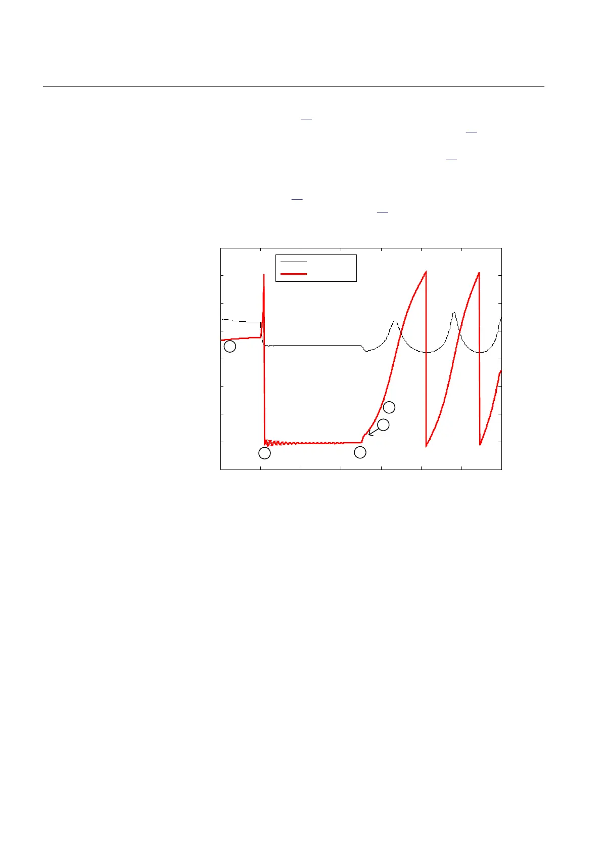
from 30 to 60 electrical degrees. It can be observed in Figure
62 that the angle
reaches 180 degrees when the complex impedance Z(R, X) crosses the impedance
line SE – RE. It then changes the sign, and continues from -180 degrees to 0
degrees, and so on. Figure
62 shows the rotor (power) angle and the magnitude of
Z(R, X) against time for the case from Figure 61.
0 200 400 600 800 1000 1200 1400
-4
-3
-2
-1
0
1
2
3
4
Time in millis econds
®
Impedance Z in Ohm and rotor angle in radian
®
|Z| in Ohms
angle in rad
normal
load
fault 500 ms
Z(R,X) cros s e d
the impeda nce line , Z-line,
conne cting points SE - RE
fault
occurrs
Z(R, X) under fault lies
on the impedance line
or near (for 3-ph faults)
Unde r 3-pha s e fa ult
condition rotor angle
of app. ±180 de gre e s
is m ea s ure d ...
rotor (power)
angle
|Z|
IEC10000110-2-en.vsd
1
2
3
1
0
IEC10000110 V2 EN-US
Figure 62: Rotor (power) angle and magnitude of the complex impedance
Z(R, X) against the time
In order to be able to fully understand the principles of OOSPPAM, a stable case,
that is, a case where the disturbance does not make a generator to go out-of-step,
must be shown.
Section 6 1MRK 506 382-UEN A
Impedance protection
140 Line distance protection REL650 2.2 IEC
Technical manual