prefL1
prefL2
prefL3
startL1
startL3
startL2
startIN
OperMode
More
than
one
true
Preference
Scheme
INL1
INL2
INL3 OUTL3
OUTL2
OUTL1
Sheme
t
40 ms
AND
stIN
stIN40ms
IEC16000023-1-en.vsdx
IEC16000023 V1 EN-US
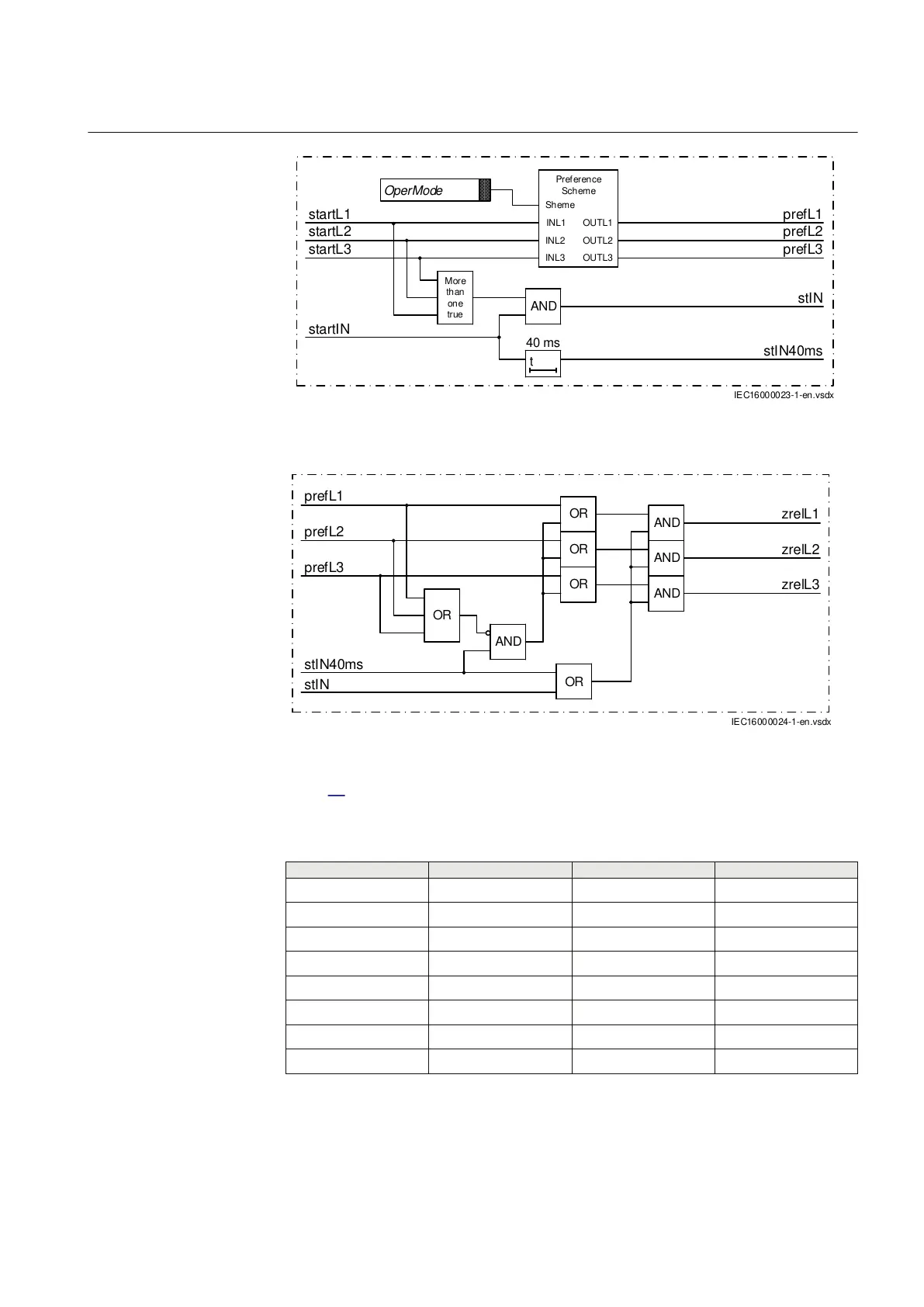
Figure 76: Phase preference 1
stIN
zrelL 1
prefL1
prefL2
prefL3
AND
OR
stIN40ms
OR
OR
OR
AND
AND
AND
OR
zrelL2
zrelL3
IEC16000024-1-en.vsdx
IEC16000024 V1 EN-US
Figure 77: Phase preference 2
Table 62 shows the preferred phase for each detected cross-country fault type and
operating mode (OperMode).
Table 62: Preferred phase for each cross-country fault type and operating mode
Operating mode
start in L1 & L2 start in L2 & L3 start in L3 & L1
1231c L1 L2 L3
1321c L2 L3 L1
123a L1 L2 L1
132a L1 L3 L1
213a L2 L2 L1
231a L2 L2 L3
312a L1 L3 L3
321a L2 L3 L3
1MRK 506 382-UEN A Section 6
Impedance protection
Line distance protection REL650 2.2 IEC 155
Technical manual