Function block SPA address CMD Input SPA address CMD output
SINGLECMD4-Cmd3 4-S-4740 5-O-561
SINGLECMD4-Cmd4 4-S-4741 5-O-562
SINGLECMD4-Cmd5 4-S-4742 5-O-563
SINGLECMD4-Cmd6 4-S-4743 5-O-564
SINGLECMD4-Cmd7 4-S-4744 5-O-565
SINGLECMD4-Cmd8 4-S-4745 5-O-566
SINGLECMD4-Cmd9 4-S-4746 5-O-567
SINGLECMD4-Cmd10 4-S-4747 5-O-568
SINGLECMD4-Cmd11 4-S-4748 5-O-569
SINGLECMD4-Cmd12 4-S-4749 5-O-570
SINGLECMD4-Cmd13 4-S-4750 5-O-571
SINGLECMD4-Cmd14 4-S-4751 5-O-572
SINGLECMD4-Cmd15 4-S-4752 5-O-573
SINGLECMD4-Cmd16 4-S-4753 5-O-574
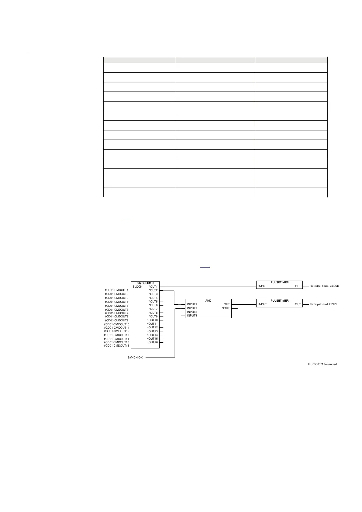
Figure 358 shows an application example of how the user can, in a simplified way,
connect the command function via the configuration logic circuit in a protection
IED for control of a circuit breaker.
A pulse via the binary outputs of the IED normally performs this type of command
control. The SPA addresses to control the outputs OUT1 – OUT16 in
SINGLECMD:1 are shown in table
522.
SINGLECM D
BLOCK ^OUT1
^OUT2
^OUT3
^OUT4
^OUT5
^OUT6
^OUT7
^OUT8
^OUT9
^OUT10
^OUT11
^OUT12
^OUT13
^OUT14
^OUT15
^OUT16
AND
INPUT1
INPUT2
INPUT3
INPUT4
OUT
NOUT
PULSETIMER
INPUT OUT
#CD01-CMDOUT1
#CD01-CMDOUT2
#CD01-CMDOUT3
#CD01-CMDOUT4
#CD01-CMDOUT5
#CD01-CMDOUT6
#CD01-CMDOUT7
#CD01-CMDOUT15
#CD01-CMDOUT16
#CD01-CMDOUT8
#CD01-CMDOUT9
#CD01-CMDOUT10
#CD01-CMDOUT11
#CD01-CMDOUT12
#CD01-CMDOUT13
#CD01-CMDOUT14
SYNCH OK
PULSETIMER
INPUT OUT
To output board, CLOSE
To output board, OPEN
IEC05000717-4-en.vsd
IEC05000717 V4 EN-US
Figure 358: Application example showing a simplified logic diagram for control
of a circuit breaker
The MODE input defines if the output signals from SINGLECMD:1 is off, steady
or setable pulse length signals. This is set in Parameter Setting Tool (PST) under:
Main Menu/Settings / IED Settings / Control / Commands / Single Command
or via Parameter Setting Tool (PST).
Section 17 1MRK 506 382-UEN A
Station communication
734 Line distance protection REL650 2.2 IEC
Technical manual