10-92
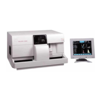
CELL-DYN
®
3200 System Operator’s Manual
9140181H—October 2001
Troubleshooting and Diagnostics
Tables for Instrument Conditions and Messages
Section 10
The FAULT indicator light on the Analyzer status indicator panel is
illuminated in red
NOTE: This type of fault is usually accompanied by a message in the status box
and/or on the bulletin line.
––– -Probable Cause–––– ––– -Corrective Action–––
1. The Analyzer has detected a fault
situation and has stopped operating.
1. From the first DIAGNOSTICS MENU
screen, press[FAULT REPORT]. Print
a copy of the report and perform the
indicated corrective action. When
the action is completed, initialize the
Analyzer by pressing the
[INITIALIZATION] key on the second
DIAGNOSTICSMENU screen.
2. If the fault report does not indicate a
message or action, document the
situation and initialize the Analyzer
by pressing the [INITIALIZATION] key
on the second DIAGNOSTICS MENU
screen.
The message “Please check signal cable” appears on the Display Monitor
––– -Probable Cause–––– ––– -Corrective Action–––
1. The Display Monitor interface cable
is not securely connected.
1. Locate the VGA connector (25 pin)
on the Rear Panel of the Data
Module. Reseat the cable and secure
the connection properly.
2. Defective Data Module component. 2. Contact your Abbott Hematology
Customer Support Center.
Table 10.4 Non-Functional Fault Conditions (Continued)