CELL-DYN
®
3200 System Operator’s Manual
2-15
9140181K—July 2002
Section 2 Installation Procedures and Special Requirements
Sample Loader Inspection (SL Model)
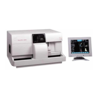
The Sample Loader is attached directly to the Analyzer to form an integrated unit,
as shown in Figure 2.8.
Four screws, two on either side, hold the Sample Loader to the Analyzer. A power
cord provides power from the Analyzer to the loader, and an interface cable allows
communication between the Analyzer and loader. The Analyzer and Sample
Loader are also connected by two quick-disconnect tube lines, one for pressure and
one for vacuum.
The tube spinning and sample aspiration mechanism on the Tower Module is
identical on both the SL and CS models. The Tower Cover on the SL model differs
from its counterpart on the CS model in two ways:
1. It is larger in order to extend over the center portion of the Sample Loader
which contains the Bar Code Reader and Mixing Assembly.
2. It serves as a safety cover, halting operation of the Sample Loader if it is
removed.
Figure 2.8 Analyzer With Sample Loader