Mechanical mounting
DLT-V83 Operating Instructions V2.00 121 / 157
13.4. Attaching device mounting and accessory mounting (optional)
Observe the following information about the mounting brackets:
− All mounting brackets and mounting parts supplied by Advantech are only intended to be used for
attachment of the Industrial Computers and the peripheral devices and may not be misused.
− Only use suitable mounting brackets and screws permitted by Advantech.
− Ensure that ball-and-socket bases and mounting brackets are always attached correctly.
Risk of accident on vehicles if the mounting becomes loose.
− Mechanical expert knowledge is required for correct attachment of device mounts and accessory
mounts on the DLT-V83.
− Use suitable mounting material.
− Observe the maximum screw-in depth of the holes of the DLT-V83:
− The recommended screw-in depth of D x 1 always applies (screw diameter x 1).
− NOTICE: Screws that are too long, e.g. in the VESA mounting holes, can pierce the rear side of
the DLT-V83 and cause irreparable damage to the device.
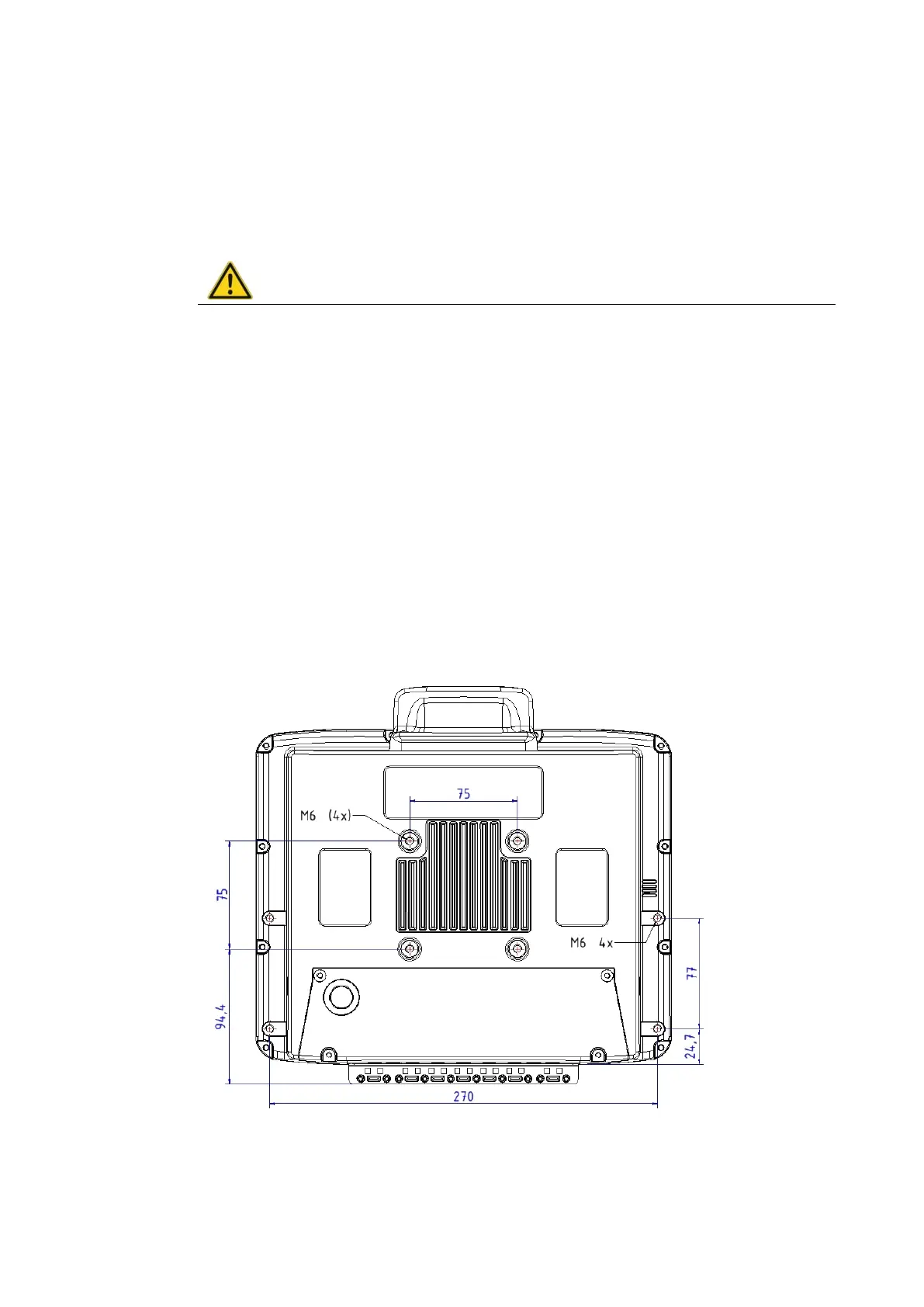
13.4.1. VESA drill holes
VESA-compatible drilling patterns for the RAM attachment and swivel joint brackets are located on the
rear side of the DLT-V83.
DLT-V8310 VESA drill holes
Dimensions without add-ons (in mm)
Depth of thread: M6 x 6mm
Fig. 13.1: Position of the VESA drill holes DLT-V8310