3. If the resistance is correct.
Test the main harness circuit between the sensor connector
terminals and the corresponding pin terminals at the ECU (see
wiring diagram).
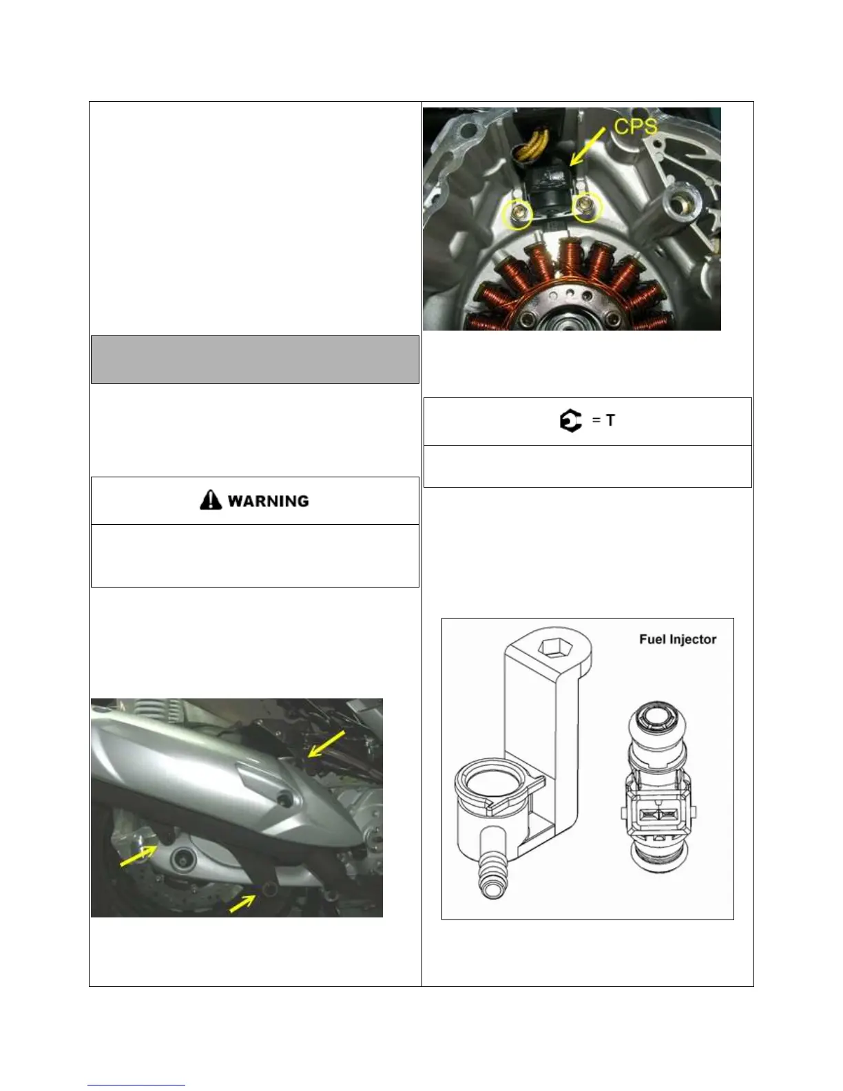
Check the sensor mounting, air gap, flywheel ring gear for
damage or run out, and flywheel key. Follow the “CPS
Replacement” procedure to inspect CPS and flywheel ring
for damage.
4. If the resistance is incorrect, follow the “CPS Replacement”
procedure.
CPS Resistance Specification:
110~500Ω
ΩΩ
Ω(25℃
℃℃
℃ / 77℉
℉℉
℉)
CPS REPLACEMENT
Removal
1. Safely support the rear of the vehicle off the ground and
remove the left-hand rear tire.
Serious injury may result if machine tips or falls.
Be sure the vehicle is secure before beginning
service procedure.
2. Remove seat.
3. Remove storage box.
4. Remove right side service panel.
5. Remove right side footwall panel.
6. Remove exhaust pipe and silencer.
7. Drain all engine oil.
8. Remove 10 bolts retain on right crankcase.
9. Remove right crank-cover which with stator and CPS.
10. Remove 2 retains bolts and the CPS.
11. Install new sensor.
12. Torque the CPS retaining bolt to specification.
CPS Retaining Bolt Torque:
2.5 Nm (22 in. lbs.)
FUEL INJECTOR OPERATION OVERVIEW
The fuel injector mount into the cylinder head, and the fuel rail
attaches to them at the top end. Replaceable O-rings on both
ends of the injector prevent external fuel leaks and also
insulate it from heat and vibration.
When the key switch is on, the fuel rail is pressurized, and
voltage is present at the injector. At the proper instant, the
ECU completes the ground circuit, energizing the injector.