The terminal connections for switches (main switch, handlebar
switch, engine stop switch, light switch, etc.) are shown in a
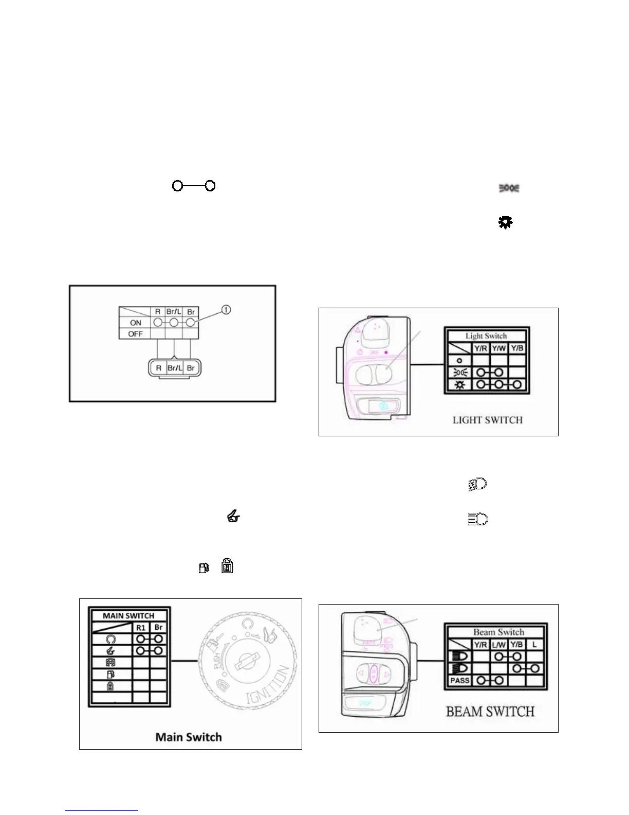
chart similar to the one on the right.
This chart shows the switch positions in the column and the
switch lead colors in the top row.
For each switch position, “ ” indicates the
terminals with continuity.
The example chart shows that:
There is continuity between the “Red, Brown/
Blue, and Brown” leads when the switch is set to
“ON”.
KEY / MAIN SWITCH
1. When the key switch is turned to the “ON” position, there
should be continuity between the red (R1) and brown (Br)
wires.
2. When the key is turned to the “OFF” position, there should
no continuity between any of the wires.
3. When the key switch is turned to the “ ” seat open
position, there should be continuity between the red (R1) and
brown (Br) wires.
4. When the key is turned to the “ ” “
”
position, there
should no continuity between any of the wires.
HEADLIGHT SWITCH
Headlight switch include light and beam switch which light
switch local on handlebar by right side and beam switch local
on handlebar by left side.
Light Switch
1. When the headlight switch is pushed to the “ ” position,
there should be continuity between the (Y/R & Y/W) wires.
2. When the headlight switch is pushed to the “ ” position,
there should continuity between the (Y/R & Y/W & Y/B)
wires.
3. When the headlight switch is pushed to the “OFF
BEAM SWITCH
1. When the beam switch is pushed to the “ ” position, there
should be continuity between the (Y/B & L) wires.
2. When the beam switch is pushed to the “ ” position, there
should be continuity between the (L/W &Y/B) wires.
3. When the beam switch is pressed to the “ BOTH” position, there
should be continuity between the (Y/R & L/W) wires. Both headlights