VOLTAGE DROP TEST
The Voltage Drop Test is used to test for bad connections.
When performing the test, you are testing the amount of
voltage drop through the connection. A poor or corroded
connection will appear as a high voltage reading. Voltage
drop shown on the meter when testing connections should not
exceed 0.1 VDC per connection or component.
To perform the test, place the meter on DC volts and place the
meter leads across the connection to be tested. Refer to the
chart on next page to perform voltage drop tests on the starter
system.
Voltage Drop should not exceed: 0.1 DC volts per
connection
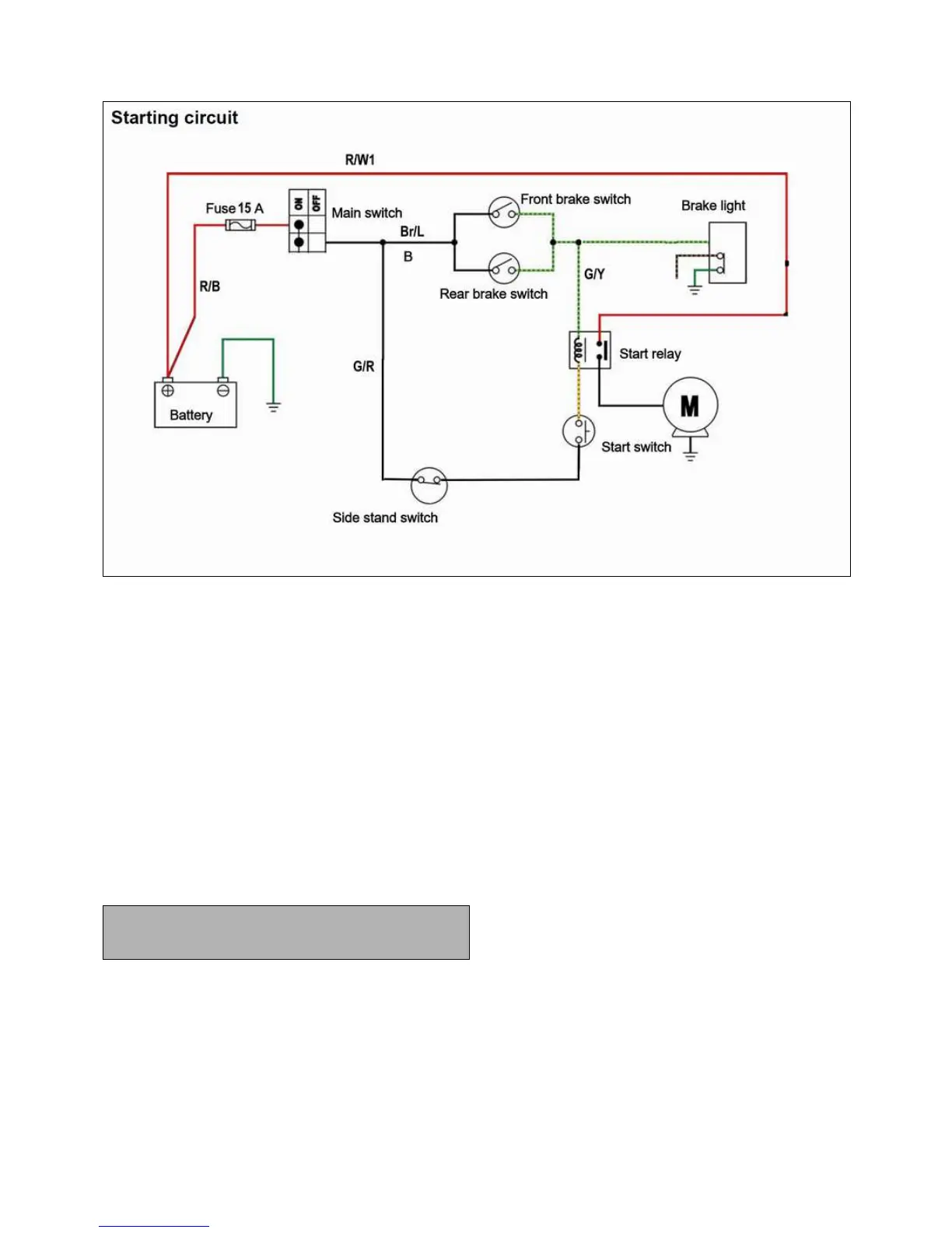
Use the illustration above and procedure below when
troubleshooting a “No Start” condition.
STARTING CIRCUIT OPERATION
The starting circuit on this model consists of the starter motor,
starter relay, brake light switch, and ECU and kick stand switch
If the main switch is “START” position, the starter motor can
be operated only if:
1. The kickstand on ground (kickstand tough ground). Or
2. The brake lever is not pressed (the brake light switch is
closed).
IF THE STARTING MOTOR FAILS TO OPERATE
FOLLOWING PROCEDURE TO CHECKING.
◎
◎◎
◎ FUSE
Ensure fuse (main, ignition, signaling system) continuity. If
broken, replace the fuse.
◎
◎◎
◎ BATTERY
Check the battery condition. The open-circuit voltage should be
12.8 V or more at 20 °C (68 °F).
If battery less than 11.8V inspect regulator and stator, recharge
or replace the battery.