4. Turn the main switch” on” and apply brake lever. Connect
probe (+) into “Y/W” and probe (-) into “B”.
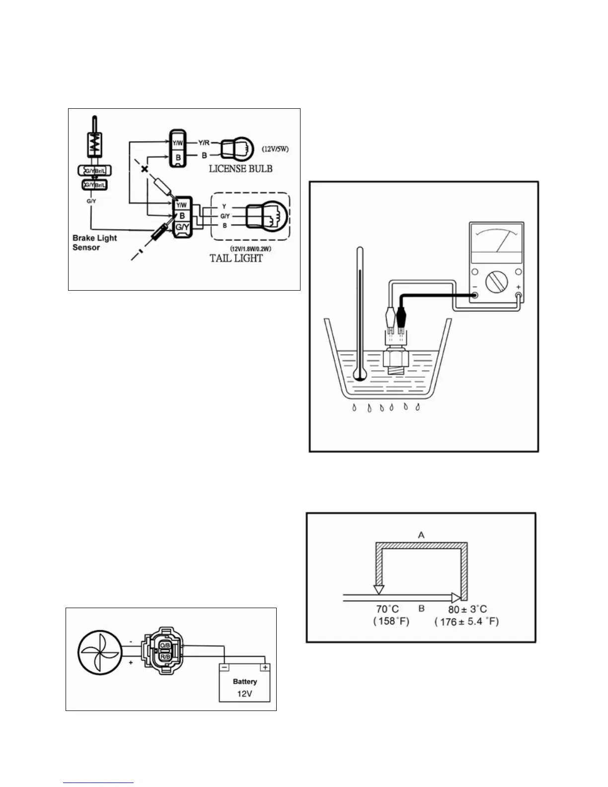
5. Check the voltage (12 V) of the “G/Y” and “B” terminals on
the taillight bulb socket and foot brake pedal sensor connector.
6. If the wiring circuit from the main switch to the bulb socket
connector is faulty, repair it.
COOLING SYSTEM
IF THE FAN MOTOR DOES NOT TURNING,
FOLLOWING PROCEDURE TO CHECKING.
◎
◎◎
◎ Fuse
Check the fuse (main) continuity. If broken, replace the fuse.
◎
◎◎
◎ Battery
Check the battery condition. The open-circuit voltage should
be 12.8 V or more at 20 °C (68 °F).
◎
◎◎
◎ Main Switch
Refer to “KEY/MAIN SWITCH” at above. If main switch
isn’t continuity, replace the main switch.
◎
◎◎
◎ RADIATOR FAN MOTOR
1. Disconnect the radiator fan motor coupler.
2. Connect the battery (12 V) as shown.
3. Check the operation of the radiator fan motor. If the fan
does not run, replace it.
◎
◎◎
◎ THERMO SWITCH
1. Remove the thermo switch 3 from the radiator.
2. Connect the multi-meter (Ωx 1) to the thermo switch.
3. Immerse the thermo switch into hot water.
4. Check the thermo switch for continuity.
While heating the coolant use a thermometer to record the
temperatures.
Note:
A, The thermo switch circuit is closed.
B. The thermo switch circuit is open.