CVT SYSTEM
3-38
DRIVE CLUTCH SERVICE
CVT Drive Belt Width
Service Limit: 24mm
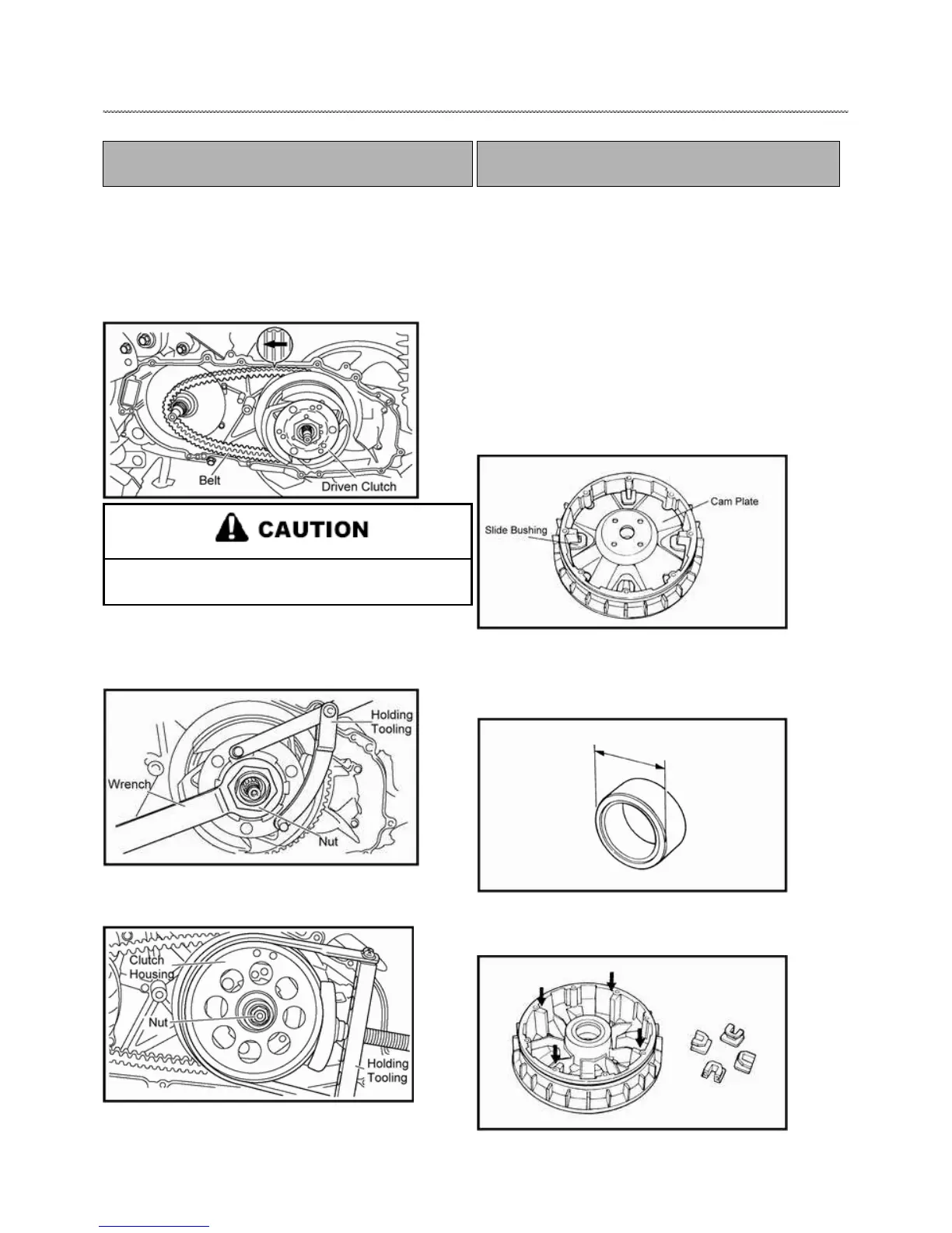
4. Install the drive clutch assembly into Crankshaft.
5. Install the drive belt on driven clutch sheave side and move
belt as far into the sheaves as possible.
6. Install the V-belt with the printed arrow mark on the V-belt
facing in the direction shown in the illustration.
Do not allow grease to contact the V-belt and the
secondary sheave assembly.
7. Holding the clutch shoe assembly with the holding tool
tighten the clutch shoe assembly nut to 90Nm with the locknut
wrench.
8. Hold the clutch housing with the holding tooling;
clutch-housing nut to 50Nm.
Driven Assembly Nut Torque
50 Nm (37 ft. lbs.)
DRIVE CLUTCH DISASSEMBLT AND
INSPECTION
1. Remove outer drive clutch sheave and drive belt. Note parts
assembly order.
2. Slide sheave and cam plate off crankshaft as an assembly.
NOTE: When removing primary sliding sheave and
cam plate assembly, hold cam plate and sliding
sheave together. This prevents the rollers from
out of the assembly.
3. Remove cam plate.
4. Inspect surface of roller weight for wear or damage. The
outside diameter is 23.2mm and the service limit is 22.7mm.
5. Inspect surface of slide sheave; slide bushing and cam plate
for wear, pitting, or damage.