GENERAL INFORMATION
ELECTRICAL SYSTEM SERVICE NOTE
Reference the following notes when diagnosing electrical
problems.
• Refer to wiring diagram for stator and electrical
component resistance specifications.
• When measuring resistance of a component that has a low
resistance value (under 10 Ohms), remember to subtract
meter lead resistance from the reading.
Connect the leads together and record the resistance.
The resistance of the component is equal to tested value
minus the lead resistance.
• Become familiar with the operation of the meter. Be sure
leads are in the proper jack for the test being
10A jack for current readings). Refer to
included with the meter for more information.
• Voltage, amperage, and resistance values included in this
manual are obtained with a Digital Multi-meter. This meter
is acceptable for use when diagnosing electrical problems.
Readings obtained with other meters may differ.
• Pay attention to the prefix on the multi-meter reading (K,
M, etc.) and the position of the decimal point.
• For resistance readings, isolate the component to be
tested. Disconnect it from the wiring harness or power
supply.
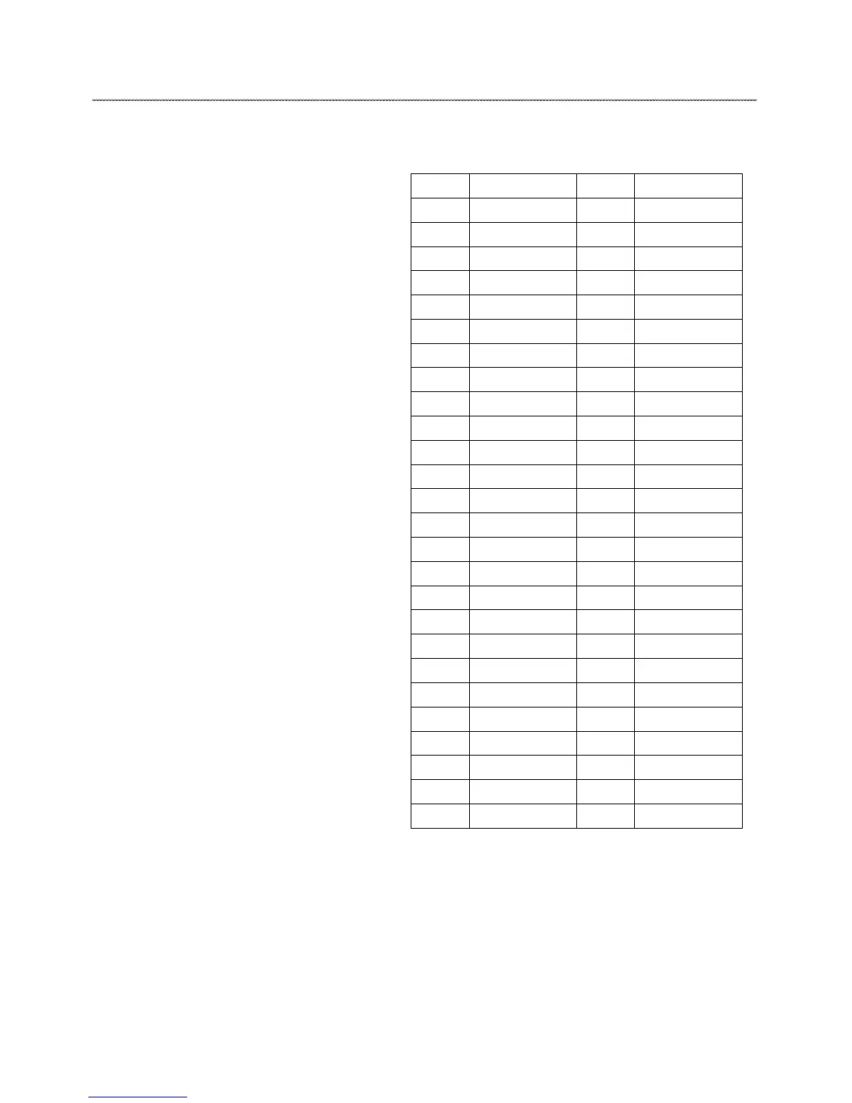
WIRES COLOR LETTER LIST
Letter Color Letter Color
B
Black
L/W
Blue/ White
B/G
Black/ Green
L/Y
Blue/Yellow
Bl
Black
L/G
Blue/ Green
B/L
Black/Blue
O
Orange
B/R
Black/Red
O/B
Orange/Black
B/W
Black/ White
P
Pink
B/Y
Black/Yellow
Pu
Purple
Br
Brown
R
Red
Br/L
Brown/Blue
R/B
Red/Black
Br/W
Brown/White
R/W
Red/White
Br/B
Brown/ Black
R/Y
Red/ Yellow
Br/Y
Brown/ Yellow
R/O
Red/ Orange
C
Cyan
W
White
C/R
Cyan/
WB
Water Blue
DB
Deep Brown
W/B
White/Black
DG
Deep Green
W/L
White/Blue
G
Green
W/R
White/Red
G/R
Green/Red
W/G
White/Green
G/W
Green/White
W/Br
White/Brown
G/Y
Green/ Yellow
W/Y
White/Yellow
Gr
Gray
Y
Yellow
Gr/ R
Gray/ Red
Y/B
Yellow/ Black
G/L
Green/ Blue
Y/L
Yellow/ Blue
L
Blue
Y/R
Yellow/ Red
L/R
Blue/ Red
Y/W
Yellow/ White
L/B
Blue/ Black