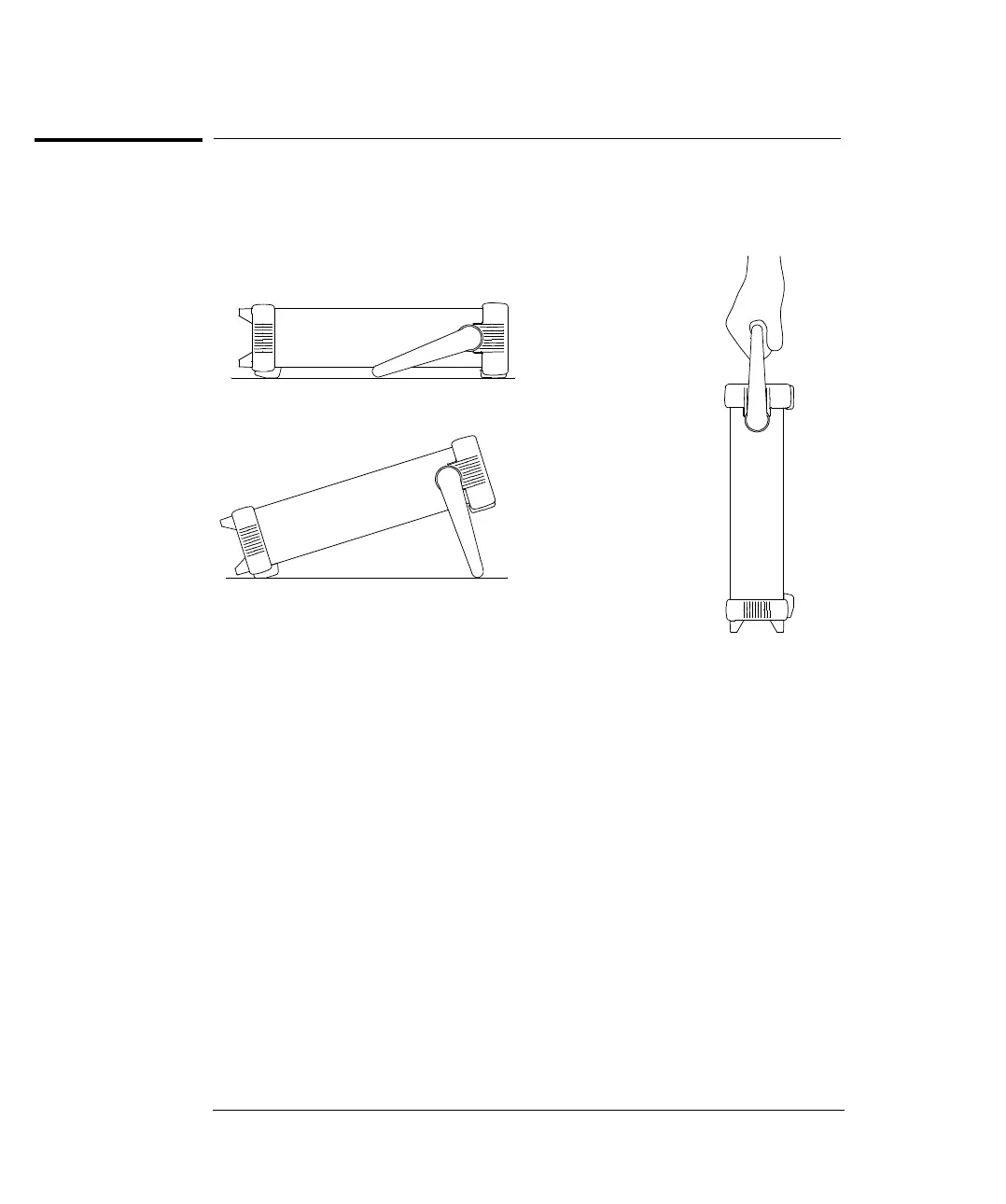
To Adjust the Carrying Handle
To adjust the position, grasp the handle by the sides and pull outward.
Then, rotate the handle to the desired position.
Bench-top viewing positions
Carrying Position
Chapter 1 Quick Start
To Adjust the Carrying Handle
16