46 5000 Series Oscilloscopes Service Guide
2 Testing Performance
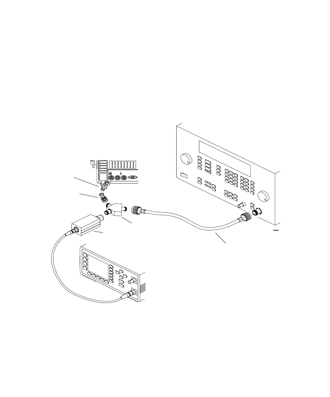
1 Connect the equipment (see Figure 6).
a Use the N cable to connect the signal generator to the
power splitter input.
b Connect one output of the power splitter to the Aux Trig
input through a 50Ω feedthrough termination.
c Connect the power sensor to the other output of the power
splitter.
Figure 6 Connect equipment for external trigger sensitivity test
(4-channel models)
Oscilloscope
Signal
Generator
Power Meter
Power Splitter
Power Sensor
N to BNC adapter
N Cable
50Ω Feedthrough*
* Required for all models.
 Loading...


