Return Loss Measurement A Background to Return Loss Measurement with the HP 81534A
148 Agilent 8163A Lightwave Multimeter, Agilent 8164A Lightwave Measurement
System, & Agilent 8166A Lightwave Multichannel System, Fourth Edition
Calculating the Return Loss of the DUT
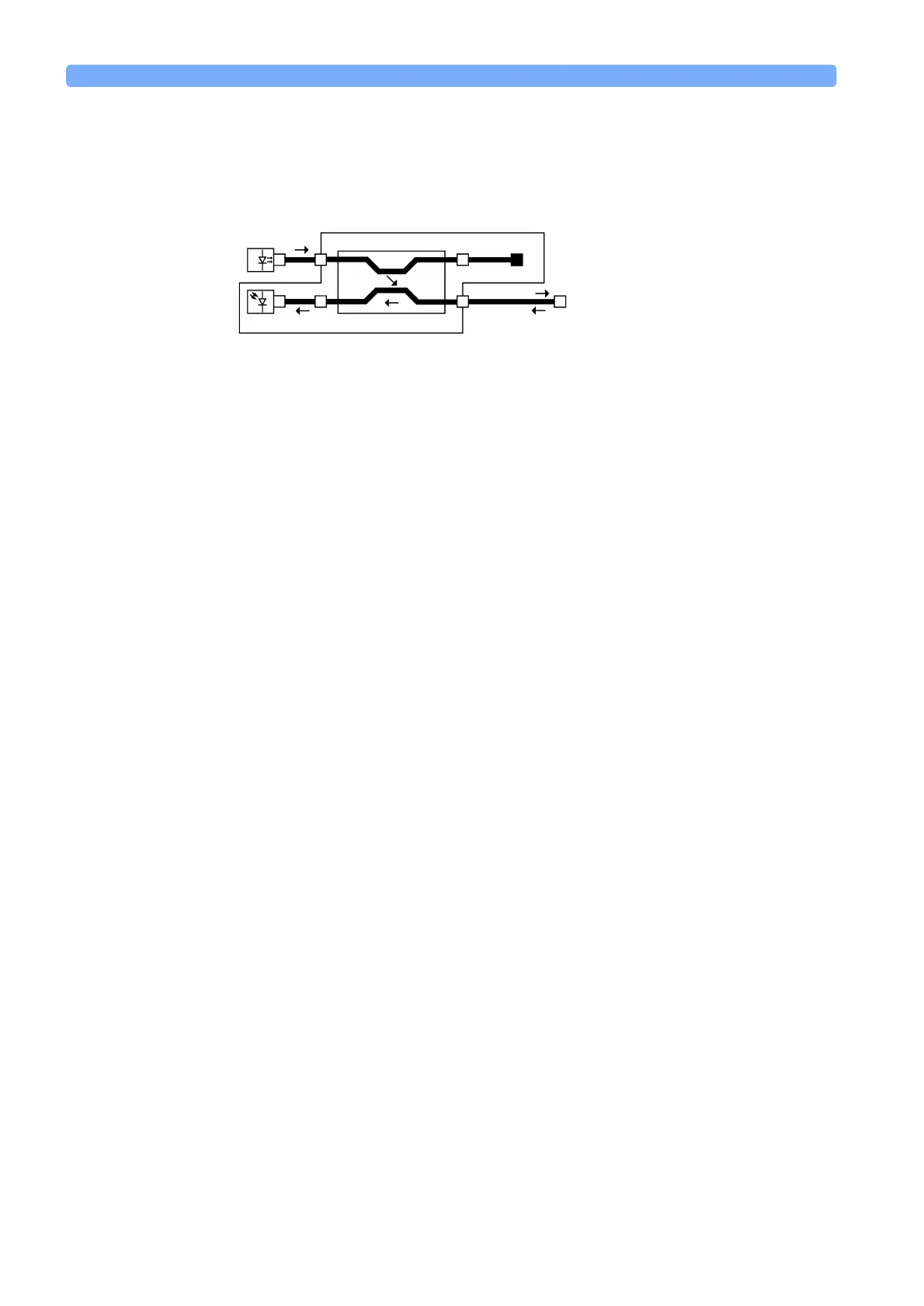
The system may be represented by the general diagram shown in Figure 106.
The reflected power, measured by the instrument, (P), from the component with
the known reflection factor, is given by the sum of:
• the part of the power, reflected by the component, which is transmitted through
the coupler, and
• the reflections due to the measurement system.
That is:
The constants k
1
and k
2
are multipliers giving the proportion of power transmitted
through the coupler from the Input port to the Output port and from the Output
port to the sensor port respectively. In other words, when optical power is input at
the Output port, k
2
times that power is output at the sensor port. It is not necessary
to know the value for these constants, they can be eliminated later.
The constant s is a multiplier giving the scattering factor. The scattering factor
accounts for the directivity of the second coupler, backscatter in the fiber, and
reflections of connectors. The calibration procedure helps you to eliminate the
affect of these on return loss measurements.
For “How to Make Return Loss Measurements with the HP 81534A Return Loss
Module” on page 135, the reflection factor of the component is known. Here we
refer to the reflection factor as R
Ref
. This gives the following equation:
For “Measuring the Power when there are No Reflections” on page 146, the
value of the reflection factor is zero. This gives the following equation:
Figure 106 Generalization of a Return Loss Measurement
HP 81534A
P
in
P
r
P
src
P
k
1
k
2
Reflectivity
R
Pk
1
k
2
RP
src
sP
src
+=
(1)
P
Ref
k
1
k
2
R
Ref
P
src
sP
src
+=
(2)
P
T
sP
src
=
(3)
 Loading...


