Installation and Maintenance Input and Output Connectors
216 Agilent 8163A Lightwave Multimeter, Agilent 8164A Lightwave Measurement
System, & Agilent 8166A Lightwave Multichannel System, Fourth Edition
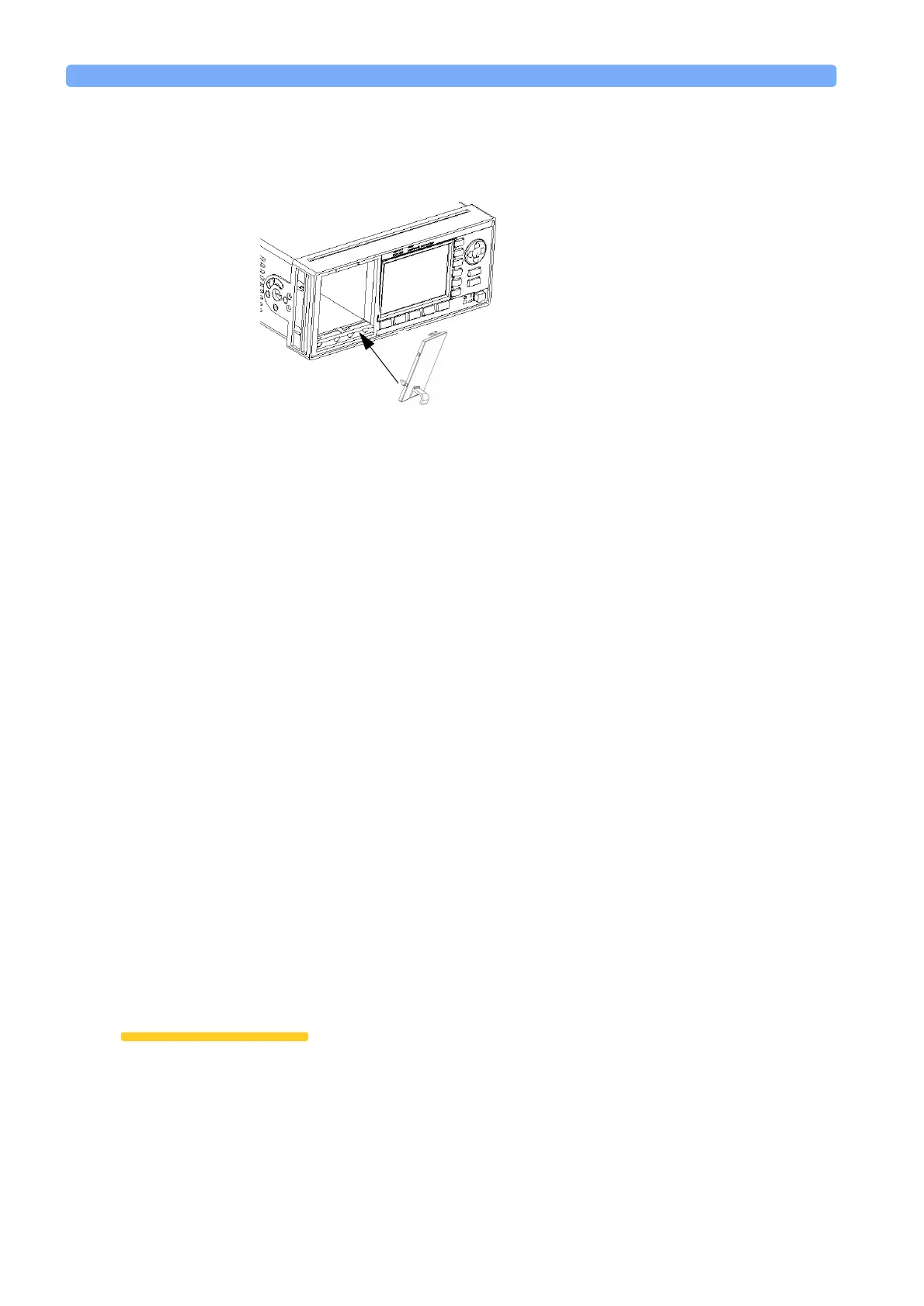
1 Position the blind panel as shown in Figure 166. Position the end closest to the
handle against the bottom edge of the slot.
2 Push the top of the blind panel so that it clicks into position.
NOTE To remove a blind panel, pull the handle.
Fitting a Filler Module for Back-Loadable Module
Slots
The Agilent 81645A Filler Module must be used if you have not installed a back-
loadable Tunable Laser module into the Agilent 8164A Lightwave Measurement
System.
The Agilent 81645A Filler Module can be fitted in the same way as any back-
loadable module, see “How to Fit and Remove Modules” on page 210.
The Agilent 81645A Filler Module can be removed in the same way as any back-
loadable module, see “How to Remove a Back-Loadable Module” on page 211.
Input and Output Connectors
There are three BNC connectors on the rear panel of your instrument. These are
the Remote Interlock, the Trigger Out and the Trigger In connectors.
CAUTION There are two input BNC connectors: the Remote Interlock Connector and the
Trigger Input, see Figure 167 or Figure 168. These are TTL inputs. A maximum
of 5 V can be applied as an external voltage to either of these input connectors.
Figure 166 Fitting a Blind Panel

 Loading...


