4. Configuration
101
Add and configure the MODBUS mappings, specifying the variable name, data type, data initial
address, data size and variable that will receive the quality data.
Add and configure the MODBUS request, specifying the desired function, the scan time of the
request, the initial address (read/write), the size of the data (read/write), the variable that will
receive the data quality, and the variable responsible for disabling the request.
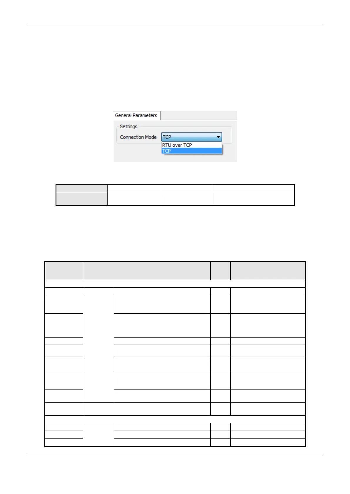
MODBUS Client Protocol General Parameters – Configuration via Symbolic Mapping
The general parameters, found on the MODBUS protocol configuration initial screen (Figure 4-29),
are defined as:
Figure 4-29. MODBUS Client General Parameters Configuration Screen
Table 4-65. MODBUS Client General Configurations
The MODBUS Client protocol diagnostics and commands configured, either by symbolic mapping
or direct representation, are stored in T_DIAG_MODBUS_ETH_CLIENT_1 variables. For the direct
representation mapping, they are also in 4 bytes and 8 words which are described in Table 4-66
(where “n” is the configured value in the %Q Initial Address of Diagnostic Area field).
Direct
Representation
Variable
Diagnostic Variable
T_DIAG_MODBUS_ETH_CLIENT_1.*
The client is in execution mode
The client is not in execution
mode (see bit
bInterruptedByCommand)
The bit bNotRunning was
enabled, as the client was
interrupted by the user through
command bits
Indicates if there is failure in the
module or the module is not
present
Indicates that all devices
configured in the Client are in fail
Command bits, automatically initialized:
Restart the diagnostic statistics
 Loading...