4. Configuration
117
Note:
Counters: all counters of the MODBUS Ethernet Server Diagnostics return to zero when the limit
value 65535 is exceeded
Mapping Configuration – Configuration via Symbolic Mapping
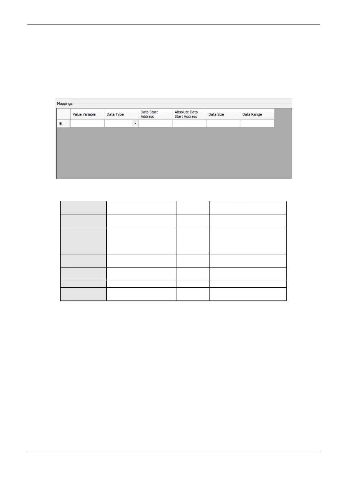
The setting of the MODBUS Server mappings, visualized in Figure 4-39, follows the parameters
described in Table 4-82.
Figure 4-39. MODBUS Server Data Mappings Screen
Name of a variable declared in a
program or GVL
Coil
Input Status
Holding Register
Input Register
Starting address of the
MODBUS data
Absolute Data
Start Address
Start address of absolute data
of Modbus as its type
The data range address
configured
Table 4-82. MODBUS Ethernet Mappings Configuration
Notes:
Value Variable: this field is used to specify a symbolic variable in MODBUS relation.
Data Type: this field is used to specify the data type used in the MODBUS relation.
Data Start Address: data initial address of the MODBUS relation.
Absolut Data Start Address: Absolute start address of the MODBUS data according to their type.
For example, the Holding Register with address 5 has absolute address 400005. This field is read
only and is available to assist in Client / Master MODBUS configuration that will communicate with
this device. The values depend on the base address (offset) of each data type and allowed MODBUS
address for each data type.
Data Size: the Data Size value sets the maximum amount of data that a MODBUS relation can
access from the initial address. Thus, in order to read a continuous range of addresses, it is necessary
that all addresses are declared in a single relation. This field varies according to the configured type
of MODBUS data.
 Loading...